
Specifications


Circuit Board Troubleshooting 47
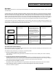
Circuit Board Troubleshooting
Error Mode
When a failure is detected, the control will generate and display an error or alarm code, depending on the type of failure, as shown
in the table below.
In order to clear an error code (after correcting the problem), push and hold the “Status” key for 10 seconds. After the 10 seconds,
the control will clear the error code and cycle the valve to service (Home). Other methods of clearing the error code are: powering
down the control for 60 seconds, toggling a DIP switch or changing an input connection (adding or removing a Flow Meter). If the
problem is still present after clearing the error code, the error code will again be displayed. While in error mode, the control will not
function. When returning from Error mode, the control shall use the values stored in EEPROM unless a DIP switch was toggled or
an input connection (Flow Meter) was changed. In those cases, the programmed values shall revert back to the defaults.
For E2 and E3 errors, the control is to attempt to return to home and stop. If the control is successful in nding and stopping in the
home position it is to display the error code but return to functioning as normal. If the next regeneration is successful without errors
the error code is to be removed and the control will function as normal.
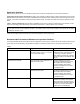
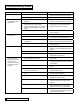
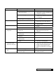
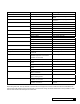
Display Error Description Mode of Detection Clearing Error / Alarm
Motor Failure to Start (No
switch changes)
If the valve fails to reach
the desired state within 70
seconds of driving the motor.
The control will attempt to
start the motor 3 times for 70
seconds each time with a 60
second off period between
each attempt.
Press and hold ‘STATUS’ key
for 10 seconds
Motor Failure to Stop
(unexpected switch changes)
If the control detects changes
in the Cam inputs when the
motor is not supposed to be
turning
Press and hold ’STATUS’ key
for 10 seconds
Incorrect Cycle Position
(switch changes out of
sequences)
The control expects to be in
a different position than that
indicated by the Cam switch
closures
Press and hold ‘STATUS’ key
for 10 seconds
Circuit Board Troubleshooting
Most circuit board problems are caused by outside inuences and it is not the board itself. Replacing the board may seem to work
only because the cause hasn’t reappeared – yet.
Let’s start with what to check when you come upon a circuit board problem:
1. Are those switches aligned too closely to the cam?
There should be a small but obvious gap between the switches and the cam so that a “wobbling cam” doesn’t accidentally
bump the switch.
2. Has the seal pack been checked for free movement?
Feedback and experience has demonstrated that seal packs that are over-tightened create drag on the motor and delays
that would result in an error code: If the motor never stops (still runs after the desired position is sensed, causing unexpected
switch closures) OR if the motor gets stuck “timing out” and the control never sees any switch action.
3. Are all the wiring terminals tightly connected?
Sometimes a loose or poorly connected wire can give feedback to the board that would result in an error code or default.
4. After checking all of these possibilities you should run the diagnostics (test mode) on the board
Instructions are listed on page 48.