
Specifications
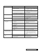

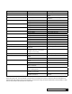


50 Culligan Medallist Series
®
Familiarize yourself with the replacement procedures and component parts thoroughly before attempting any repair.
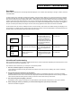
Circuit Board
To replace the AccuSoft
™
circuit board, refer to gure 23 and the parts list and proceed as follows:
1. Lift up the front cover of the control.
2. Remove all connected wire leads from the board.
3. Remove the circuit board from the retaining clips on
the front cover.
4. The new circuit board can be installed by reversing the
steps 1-3 above.
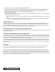
Refer to Figure 24 for assembly and disassembly of the various valve components.
Caution! Grip all connections to the
circuit board by the connecting terminals
for assembly and disassembly. Failure to
do so could result in damage to the wire
leads or connecting terminals.
Warning! Disconnect all electrical power to the unit before servicing. Bypass the unit and relieve system
pressure before attempting to repair.
Caution! Do not touch any surfaces of the
circuit board. Electrical static discharges
may cause damage to the board. Handle
the AccuSoft circuit board by holding
only the edges of the circuit board. Keep
replacement boards in their special anti-
static bags until ready for use. Mishandling
of the circuit board will void the warranty.
Caution! The wire connectors must be connected to the circuit board properly. The wires must exit the plug-in
connector opposite of the raised white base of the circuit board connector.
Figure 23
Figure 24
Service