
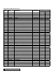
Specifications


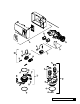

Drive Motor Assembly
1. Remove the drive motor cam switches by removing the one screw holding the switches to the motor.
2. Remove the E-ring holding the drive motor cam to the camshaft with a at tip screwdriver.
3. Lift the cam off the shaft.
4. Remove the screw above the eductor piston assembly.
5. Loosen the two screws holding the yoke support plate and the motor to the control valve.
6. Remove the yoke support plate and yoke by gently pulling them down.
7. Fully remove the two screws holding the motor to the control. The motor will pull away from the control and the backplate will
hang on the valve body.
Note: If the unit is equipped with a meter, it is recommended to unclip the meter cable from the meter body to allow backplate
movement.
Note: Care should be taken to not damage the brine piston if it is not going to be replaced. The brine piston will need to be
twisted slightly in order to remove it from the motor die casting.
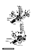
This procedure can be followed in the reverse order to reassemble the motor to the control. When reassembling the scotch yoke,
the yoke must slide into the yoke support plate prior to pushing the assembly up into the piston end and follower. Figure 25 shows
proper assembly of the yoke into the support plate.
Note: The seal pack may need to be repositioned in order for the follower to be inserted into the yoke, using the motor and
backplate to push the seal pack fully into the valve is helpful in aligning the yoke. Make sure that the follower is in the follower
slot on the yoke, and that the end of the piston rod is held in the end of the yoke.
Note: When attaching the yoke support plate be certain to push up on the plate until the two mounting screws bottom in the
U-shaped channels of the support plate.
Figure 25
Service 51