
Install Manual
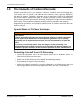
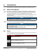
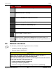

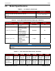

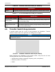
Table Of Contents
- Table of Contents
- 1. Important Safety Instructions
- 1.1 Warning, Caution, and Note Styles Used in This Manual
- 1.2 General Information
- 1.3 General Precautions
- 1.4 Generator Set Voltage Is Deadly
- 1.5 Engine Exhaust Is Deadly
- 1.6 Fuel and Fumes Are Flammable
- 1.7 Batteries Can Explode
- 1.8 Moving Parts Can Cause Severe Personal Injury or Death
- 1.9 The Hazards of Carbon Monoxide
- 2. Introduction
- 3. Pre-Installation Considerations
- 4. Installation
- 5. Startup and Configuration
- Appendix A. Fuel Line Selection
- Appendix B. Outline and System Drawings
- Appendix C. Seismic Requirements

2. Introduction 2-2016
16 A045R241 (Issue 7)Copyright © 2016 Cummins Inc.
TABLE 12. CONTROL SPECIFICATIONS (ALL MODELS)
Specification
Control Integrated microprocessor based engine, generator, transfer switch control
TABLE 13. DC SYSTEM SPECIFICATIONS (ALL MODELS)
Specification
Nominal Battery Voltage 12 VDC
Battery Group
26 standard, 34 high capacity (a high capacity battery requires an
accessory battery tray)
Battery Type Maintenance free
Minimum Cold Crank
Amps
545 standard, 850 high capacity (a high capacity battery requires
an accessory battery tray)
2.6 Transfer Switch Requirements
A transfer switch must be a part of every generator set installation. Transfer
switches transfer loads to the generator set during power outages.
NOTICE
Cummins offers a variety of transfer switches, including residential and light
commercial options.
FIGURE 1. CUMMINS TRANSFER SWITCH (RA SERIES)
Before beginning the installation of the transfer switch, verify that the unit was
correctly selected. Check the following features:
• Specifications (voltage, amperage, frequency, poles, and phases)
• Enclosure (indoor vs. outdoor)
• Model