
Install Manual

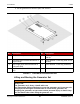


Table Of Contents
- Table of Contents
- 1. Important Safety Instructions
- 1.1 Warning, Caution, and Note Styles Used in This Manual
- 1.2 General Information
- 1.3 General Precautions
- 1.4 Generator Set Voltage Is Deadly
- 1.5 Engine Exhaust Is Deadly
- 1.6 Fuel and Fumes Are Flammable
- 1.7 Batteries Can Explode
- 1.8 Moving Parts Can Cause Severe Personal Injury or Death
- 1.9 The Hazards of Carbon Monoxide
- 2. Introduction
- 3. Pre-Installation Considerations
- 4. Installation
- 5. Startup and Configuration
- Appendix A. Fuel Line Selection
- Appendix B. Outline and System Drawings
- Appendix C. Seismic Requirements

4. Installation 2-2016
30 A045R241 (Issue 7)Copyright © 2016 Cummins Inc.
In all fuel system installations, cleanliness is extremely important.
• Make every effort to prevent fuel contamination from:
◦ Moisture
◦ Dirt
◦ Excess thread sealant
◦ Contaminants of any kind
• Clean all fuel system components before installing.
Gaseous-fuel supply system design, materials, components, fabrication, assembly,
installation, testing, inspection, operation, and maintenance must comply with the
applicable codes. See NFPA Standards No. 37, 54, and 58. For seismic installation,
refer to IBC codes and standards. Where seismic installation is required, there may
be specific anchorage requirements for the generator set and other installed
components.
Most codes require a manual shutoff valve ahead of a flexible fuel hose. The
manual valve should be of the indicating type. The generator set has electric
(battery-powered) shutoff valves included.
NOTICE
It is recommended that a shutoff valve be located near the generator set for
emergency shut off or servicing the generator set. Follow applicable codes.
Until the generator set is connected, cap the fuel line stub-up at the generator set to
prevent dirt from entering and gas from discharging if the gas supply shutoff valve is
opened accidentally.
To determine the required capacity, add generator set consumption to the gas
consumed for heating, cooking, clothes drying, etc. A typical natural gas installation
might require a 400,000 BTU meter. Consideration should also be given to utilizing
high pressure gas supply if available. This reduces the required size and cost of gas
piping, especially if the location of the generator set requires a long supply line.
Natural Gas Fuel System
Requirements for a natural gas generator set are as follows:
TABLE 15. NATURAL GAS GENERATOR SET REQUIREMENTS
Component Description
Gas Pipeline quality
Fuel Supply Adequate fuel supply to operate correctly and
run at full load
Shutoff Valve Manual