
Install Manual


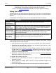
Table Of Contents
- Table of Contents
- 1. Important Safety Instructions
- 1.1 Warning, Caution, and Note Styles Used in This Manual
- 1.2 General Information
- 1.3 General Precautions
- 1.4 Generator Set Voltage Is Deadly
- 1.5 Engine Exhaust Is Deadly
- 1.6 Fuel and Fumes Are Flammable
- 1.7 Batteries Can Explode
- 1.8 Vented Batteries
- 1.9 Moving Parts Can Cause Severe Personal Injury or Death
- 1.10 The Hazards of Carbon Monoxide
- 2. Introduction
- 3. Pre-Installation Considerations
- 4. Installation
- 5. Startup and Configuration
- Appendix A. Fuel Line Selection
- Appendix B. Outline and System Drawings
- Appendix C. Wiring Diagrams
- Appendix D. Seismic Requirements

4. Installation3-2016
31A051X873 (Issue 5) Copyright © 2016 Cummins Inc.
• Install the propane tanks according to all national and local codes and
standards, and as required by the fuel tank and fuel supplier.
Refer to the Fuel Line Selection appendix for propane figures and tables.
Sizing Fuel Lines
Incorrect fuel line size may cause the generator set to not run or provide full power
output. Fuel line sizes for installations typically range from 1/4 to 2 or more inches in
diameter.
To determine the optimal fuel line size, the following information is needed:
Category Description
Fuel Flow
Requirements for
the Generator Set
Fuel flow requirements have a large impact on fuel line size.
Fuel Source
(Natural Gas or
Propane Vapor)
Fuel sources can affect fuel line size. Natural gas installations generally
require a higher fuel flow rate compared to propane vapor installations,
since propane has a higher energy content.
Fuel Line Length
(Including Fittings)
Factor in the equivalent lengths of all of the fittings (elbows, tees, valves)
in the installation in addition to the fuel line length. Longer lengths
require larger diameters.
Fuel Line Type
(e.g., Copper
Tubing or Iron
Pipe)
Most fuel line types are iron pipe or copper tubing. Be sure to use the
sizing chart for the fuel line type when sizing the fuel line.
There are some basic but very important steps all installers must follow to make
sure that fuel lines are sized correctly:
1. Verify adequate fuel flow, quality, and pressure available from utility connection.
2. Determine fuel requirements at full load. See the Model Specifications section
to determine the fuel flow requirements.
3. Determine equivalent length of fuel line fittings required. See the NFPA Pipe
Fittings table in the Fuel Line Selection appendix to determine the equivalent
lengths for elbows, tees, and valves. Add this length to fuel line length to
determine total equivalent length.
4. Determine required fuel line size at full load. See the Fuel Line Selection
appendix to determine the fuel line size.
To calculate the minimum pipe size:
1. Make a list of all the fittings and valves in a proposed system and add their
equivalent lengths.
2. Add all lengths of straight pipe to arrive at a total equivalent length to the
fittings/valves total.
3. Choose the applicable table based on the fuel system and fuel line material.