
Install Manual


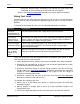
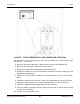
Table Of Contents
- Table of Contents
- 1. Important Safety Instructions
- 1.1 Warning, Caution, and Note Styles Used in This Manual
- 1.2 General Information
- 1.3 General Precautions
- 1.4 Generator Set Voltage Is Deadly
- 1.5 Engine Exhaust Is Deadly
- 1.6 Fuel and Fumes Are Flammable
- 1.7 Batteries Can Explode
- 1.8 Vented Batteries
- 1.9 Moving Parts Can Cause Severe Personal Injury or Death
- 1.10 The Hazards of Carbon Monoxide
- 2. Introduction
- 3. Pre-Installation Considerations
- 4. Installation
- 5. Startup and Configuration
- Appendix A. Fuel Line Selection
- Appendix B. Outline and System Drawings
- Appendix C. Wiring Diagrams
- Appendix D. Seismic Requirements

4. Installation 3-2016
32 A051X873 (Issue 5)Copyright © 2016 Cummins Inc.
4. Obtain the maximum fuel requirements for the specific generator set from the
Model Specifications section.
5. Refer to the fuel line sizing charts in the Fuel Line Selection appendix. Locate
the equivalent length of pipe (or next larger equivalent length) in the left hand
column. Move across the row to where the maximum capacity number is as
large or larger than the maximum fuel consumption (or next larger). At the top
of that column is the minimum nominal pipe size or tubing size required for the
system as designed.
Installing Fuel Lines
The basic components required for fuel line installation are as follows:
• Flexible connection
• Fuel line
• Shutoff valve
• Fuel supply
To install the fuel lines:
1. Connect a flexible fuel line to the fuel connection ports on the generator set.
2. Connect the opposite end of the flexible fuel line to the fuel source line near the
shutoff valve.
NOTICE
A shutoff valve is recommended and often required by local and state codes.
Testing the Fuel System for Leaks
After assembly and before initial operation, all of the fuel system components must
be tested and proven free of any leaks.
WARNING
Fuel presents the hazard of explosion or fire which can result in severe
personal injury or death. Do not use an open flame to check for leaks. Do not
smoke or allow any flame, spark, pilot light, arc-producing equipment, switch
or other ignition sources around fuel or fuel components. Keep multi-class
ABC fire extinguishers handy.
NOTICE
Follow any local codes and standards, as they may require a different
method or documentation of a leak test.