
Install Manual


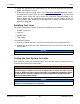
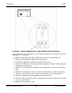
Table Of Contents
- Table of Contents
- 1. Important Safety Instructions
- 1.1 Warning, Caution, and Note Styles Used in This Manual
- 1.2 General Information
- 1.3 General Precautions
- 1.4 Generator Set Voltage Is Deadly
- 1.5 Engine Exhaust Is Deadly
- 1.6 Fuel and Fumes Are Flammable
- 1.7 Batteries Can Explode
- 1.8 Vented Batteries
- 1.9 Moving Parts Can Cause Severe Personal Injury or Death
- 1.10 The Hazards of Carbon Monoxide
- 2. Introduction
- 3. Pre-Installation Considerations
- 4. Installation
- 5. Startup and Configuration
- Appendix A. Fuel Line Selection
- Appendix B. Outline and System Drawings
- Appendix C. Wiring Diagrams
- Appendix D. Seismic Requirements

4. Installation 3-2016
36 A051X873 (Issue 5)Copyright © 2016 Cummins Inc.
FIGURE 8. CIRCUIT BREAKER AC LOAD CONNECTION LOCATIONS
For connection to the generator set, AC load connections are made in the circuit
breaker box. To access:
1. Open the enclosure side door to gain access to main circuit breaker box.
2. Place all circuit breaker handle in the OFF position.
3. Remove the eight bolts holding the circuit breaker cover.
4. Install the conductors to the circuit breaker load-side terminals, neutral lug, and
equipment grounding lug.
5. Torque the circuit breaker terminals per specifications on the circuit breaker
label.
6. Torque the neutral lug on the H & J-frame circuit breakers to 120 in-lb (14 Nm).
7. Torque the neutral lug on the L-frame circuit breakers to 442 in-lb (50 Nm).
8. Torque the equipment grounding lug to 120 in-lb (14 Nm).
9. Fill in the stub-up openings with an approved duct seal or mastic tape to keep
out insects and rodents.
10. Install the circuit breaker cover.