Owner Manual Transfer Switch RA Series 100A (Spec A) 200A (Spec A) 400A (Spec A) English Original Instructions 3-2016 A046S594 (Issue 12)
Table of Contents 1. IMPORTANT SAFETY INSTRUCTIONS ....................................................................................... 1.1 Warning, Caution, and Note Styles Used in This Manual ..................................................... 1.2 General Information ................................................................................................................ 1.2.1 Safety Precautions ...................................................................................................
Table of Contents 3-2016 5.2 Hardware Torque Specifications........................................................................................... 5.3 Switch Removal and Replacement Procedure ..................................................................... 5.3.1 Disconnect AC Power ................................................................................................ 5.3.2 Transfer Switch Assembly Removal .......................................................................... 5.3.
1 Important Safety Instructions Save these instructions. This manual contains important instructions that should be followed during installation and maintenance of the generator set. Safe and efficient operation can be achieved only if the equipment is properly operated and maintained. Many accidents are caused by failure to follow fundamental rules and precautions. 1.
1. Important Safety Instructions 3-2016 DANGER This symbol warns of immediate hazards that will result in severe personal injury or death. WARNING This symbol refers to a hazard or unsafe practice that can result in severe personal injury or death. CAUTION This symbol refers to a hazard or unsafe practice that can result in personal injury or product or property damage. 1.2.
3-2016 1.3.1 1. Important Safety Instructions AC Supply and Isolation NOTICE Local electrical codes and regulations (for example, BS EN 12601:2010 Reciprocating internal combustion engine driven generating sets) may require the installation of a disconnect means for the generator set, either on the generator set or where the generator set conductors enter a facility. NOTICE The AC supply must have the correct over current and earth fault protection according to local electrical codes and regulations.
1. Important Safety Instructions 3-2016 This page is intentionally blank. Copyright © 2016 Cummins Inc.
2 Introduction 2.1 Owner Manual This manual covers models produced under the Cummins® Power Generation (CPG) brand names. This manual provides information necessary for operation, installation, and service of RA Series transfer switches. This manual also includes parts information. This is an open transition transfer switch which does not include an integral automatic transfer switch (ATS) control. With an open transition switch, there is never a time when both sources are supplying power to the load.
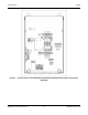
2. Introduction 3-2016 FIGURE 1. RA 100A AND RA 200A NON-SERVICE ENTRANCE TRANSFER SWITCH (WITH DOOR PANEL REMOVED) Copyright © 2016 Cummins Inc.
3-2016 2. Introduction FIGURE 2. RA 400A NON-SERVICE ENTRANCE TRANSFER SWITCH (WITH DOOR PANEL REMOVED) A046S594 (Issue 12) 7 Copyright © 2016 Cummins Inc.
2. Introduction 3-2016 FIGURE 3. RA 100A AND RA 200A SERVICE ENTRANCE TRANSFER SWITCH (WITH DOOR PANEL REMOVED) Copyright © 2016 Cummins Inc.
3-2016 2. Introduction FIGURE 4. RA 400A SERVICE ENTRANCE TRANSFER SWITCH (WITH DOOR PANEL REMOVED) A046S594 (Issue 12) 9 Copyright © 2016 Cummins Inc.
2. Introduction 2.2 3-2016 Transfer Switch Application Transfer switches are an essential part of a building's standby or emergency power system. The utility line (normal power), is backed up by a generator set (emergency power). The transfer switch switches the electrical load from one source to the other. The load is connected to the common of the ATS (Figure 5). Under normal conditions, the load is supplied with power from the utility (as illustrated).
3-2016 2. Introduction 4. Transfers the load to the generator set 5. Senses the return of utility power 6. Sends utility available signal to generator set 7. Receives retransfer command from generator set control 8. Retransfers the load to the utility The transfer switch design is intended to signal when the utility voltage is not present and when it returns. The utility sense relay coil will energize or stay energized at voltages other than nominal.
2. Introduction 3-2016 The nameplates for the RA Series transfer switches are located inside the cabinet in the following locations: • RA 100A/200A transfer switches: On the upper right side (see Figure 7 and Figure 9).
3-2016 2. Introduction FIGURE 8. RA 400A NON-SERVICE ENTRANCE NAMEPLATE A046S594 (Issue 12) 13 Copyright © 2016 Cummins Inc.
2. Introduction 3-2016 FIGURE 9. RA 100A AND RA 200A SERVICE ENTRANCE NAMEPLATE Copyright © 2016 Cummins Inc.
3-2016 2. Introduction FIGURE 10. A046S594 (Issue 12) RA 400A SERVICE ENTRANCE NAMEPLATE 15 Copyright © 2016 Cummins Inc.
2. Introduction 2.5 3-2016 Manufacturing Facilities NORTH AMERICA EMEA, CIS ASIA PACIFIC Cummins Power Generation Limited 1400 73rd Ave.
3-2016 2. Introduction • Engines-Gasoline or Engines-Diesel, • Recreational Vehicles-Equipment, or • Parts and Service If it is necessary to contact a distributor regarding the transfer switch, always give the complete Model and Serial number. This information is necessary to properly identify your unit among the many types manufactured. WARNING Removing the front door will expose the operator to hazardous voltage. Ensure that both sources are de-energized and locked out prior to removing the door.
2. Introduction 3-2016 FIGURE 12. Copyright © 2016 Cummins Inc.
3-2016 2. Introduction FIGURE 13. 2.6 RA 400A SERVICE ENTRANCE MODEL Installation Overview These installation recommendations apply to typical installations. Whenever possible, these recommendations also cover factory designed options or modifications. However, because of the many variables in any installation, it is not possible to provide specific recommendations for every situation. If there are any questions not answered by this manual, contact your nearest Cummins/Onan distributor for assistance.
2. Introduction 2.6.1 3-2016 Application and Installation Installations must be carefully planned and correctly installed for proper operation. This involves two essential elements: application and installation. Application refers to the design of the complete standby power system that usually includes power distribution equipment, transfer switches, ventilation equipment, mounting pads, cooling systems, exhaust systems, and fuel systems.
3 Installation 3.1 Installation - Mounting 3.1.1 Introduction Proper storage, installation, operation, and maintenance helps to increase the life of the transfer switch. Installation is to be done only by licensed certified electricians. WARNING AC power within the cabinet presents a shock hazard that can cause severe personal injury or death. Incorrect installation, service, or parts replacement can result in severe personal injury, death, and/or equipment damage.
3. Installation 3-2016 Choose a vibration-free mounting surface that supports the weight of the switch. Avoid locations that are near flammable liquids or gases, or are hot, moist, or dusty. WARNING An electrical arc occurs during transfer that can ignite a flammable atmosphere, resulting in severe personal injury or death. The switch must not be located near batteries, fuel tanks, solvents, or other sources of flammable liquids or gases, or in areas sharing ventilation with such sources. 3.1.
3-2016 3. Installation No. Description No. Description 1 Utility Source 6 Circuit Breaker 2 Utility Panel 7 Generator Source 3 Loads 8 Loads 4 Circuit Breaker 9 Distribution Panel 5 Transfer Switch FIGURE 15. A046S594 (Issue 12) PARTIAL COVERAGE SYSTEM (SERVICE ENTRANCE MODEL) 23 Copyright © 2016 Cummins Inc.
3. Installation 3-2016 No. Description No. Description 1 Utility Source 5 Generator Source 2 Circuit Breaker 6 All Loads 3 Transfer Switch 7 Main Breaker Panel 4 Circuit Breaker FIGURE 16. TOTAL COVERAGE SYSTEM (NON-SERVICE ENTRANCE MODEL) Copyright © 2016 Cummins Inc.
3-2016 3. Installation No. Description No. Description 1 Cummins Standby Generator 3 Automatic Transfer Panel 2 Service Entrance Box 4 Main Breaker Panel FIGURE 17. A046S594 (Issue 12) TYPICAL WALL-MOUNT INSTALLATION OF NON-SERVICE ENTRANCE MODELS 25 Copyright © 2016 Cummins Inc.
3. Installation 3-2016 No. Description No. Description 1 Utility Source 5 Generator Source 2 Circuit Breaker 6 All Loads 3 Transfer Switch 7 Main Breaker Panel 4 Circuit Breaker FIGURE 18. Copyright © 2016 Cummins Inc.
3-2016 3. Installation No. Description 1 Cummins Standby Generator 2 Automatic Transfer Panel FIGURE 19. No. 3 Description Main Breaker Panel TYPICAL WALL-MOUNT INSTALLATION OF SERVICE ENTRANCE MODELS TABLE 1. APPROXIMATE CABINET DIMENSIONS Switch Current Rating Height Width Depth Weight 100 Amp NSE 24.0 in (619 mm) 17.0 in (433 mm) 7.1 in (181 mm) 33 lb (15 kg) 200 Amp NSE 27.1 in (688 mm) 18.2 in (463 mm) 7.1 in (181 mm) 46 lb (21 kg) 100 and 200 Amp SE 23.3 in (591 mm) 19.
3. Installation 3-2016 2. Check the location to be sure that no wires or plumbing, gas, or exhaust lines run behind the wall. NOTICE For Service Entrance models with integrated circuit breakers, the National Electric Code stipulates that the installed height of the circuit breaker selector switch is not more than 6 ft 7 in. above the floor, grade, or platform. 3.
3-2016 3. Installation CAUTION Installation debris can cause equipment failure and damage. Use extreme care to keep drill chips and filings out of the relays, contacts, and other parts of the automatic transfer switch when mounting or connecting conduit. Screwdrivers should be used carefully to prevent damage to components. When installing conduit, observe the following precautions: 1. The RA Series transfer switch includes cutouts on the bottom of the cabinet for wiring.
3. Installation 3-2016 TABLE 2. SCREW TYPE TERMINALS AND TORQUE VALUES FOR EXTERNAL POWER GENERATION ON NON-SERVICE ENTRANCE TRANSFER SWITCHES Terminal Description Switch Size (Amps) Utility, Generator, and Load Terminals Cables per Pole Range of Tightening Wire Torque Sizes Neutral Bar Terminals No. of Cables Ground Terminals Range of Tightening Wire Torque Sizes No.
3-2016 3. Installation Terminal Description Switch Size (Amps) 400 Amp 3.2.2 Neutral Terminals No. of Cables 3 Range of Tightening Wire Torque Sizes 3/0 AWG to 600 MCM 275 in-lb (31 Nm) Generator Neutral Terminals No. of Cables 1 Range of Tightening Wire Torque Sizes 3/0 AWG to 600 MCM 275 in-lb (31 Nm) Ground Terminals No. of Cables 4 Range of Tightening Wire Torque Sizes #6 to 3/0 AWG 160 in-lb (18 Nm) Low Voltage Signal Connections 3.2.2.
3. Installation No. 3-2016 Description No. Description 1 Control Relay 3 Socket 2 Utility Sense Relay 4 TB4 FIGURE 20. CONTROL WIRING CONNECTIONS 3.2.2.2 Connecting the Transfer Switch to the Generator WARNING AC voltages and currents present an electrical shock hazard that can cause severe personal injury or death. Disconnect the AC power source. Make sure the generator set is not running and cannot be started.
3-2016 3. Installation TABLE 5. MAXIMUM WIRE LENGTH BY WIRE SIZE Wire Size (AWG) Distance in Feet (One Way) 16 125 14 200 12 300 10 500 The transfer switches are factory wired to provide Ground (B-) signals for all customer connections: 1. N/C or N/O Utility Source Available Indicators: Ground (B-) present when Utility Source is available (TB4-2); Ground (B-) present when Utility Source is not available (TB4-1). 2.
3. Installation 3-2016 NOTICE The mechanism is shipped in the Utility side position. For service entrance transfer switches, the circuit breaker is shipped in the Off position. Copyright © 2016 Cummins Inc.
4 Troubleshooting 4.1 Introduction This section describes troubleshooting issues, as well as the sequence of events for transfer switch operations that do not include a controller. 4.2 Troubleshooting Procedures for Experienced Service Personnel This section describes a typical transfer switch sequence of events, and provides detailed troubleshooting procedures for experienced service personnel. The troubleshooting procedures use conditional schematics and symptoms to diagnose all possible problems.
4. Troubleshooting 4.2.2 3-2016 Generator-to-Utility Sequence of Events The following steps describe what normally happens when the transfer switch is connected to the generator, utility power returns, and the switch moves from the Generator position to the Utility position. 1. The utility returns. 2. The generator control receives a ground (B-) signal from the TB4-1 utility sense relay. 3.
3-2016 4.2.5 4. Troubleshooting Troubleshooting for Transfer Switches For information on the generator controller indicator fault signals, refer to the generator service manual. The tables below list troubleshooting issues for RA Series transfer switches. WARNING AC power within the cabinet and the rear side of the cabinet door presents a shock hazard that can cause severe personal injury or death.
4. Troubleshooting 3-2016 TABLE 6. TROUBLESHOOTING THE TRANSFER SWITCH (PROBLEM #1) Problem The transfer switch failed to transfer to the generator Possible Cause Corrective Action 1. The K1 relay coil may not have received a ground (B-) signal from the controller. 2. K1 relay may malfunction. 3. There may be a defective wire. 4. The switch mechanism solenoid may be burnt out. 5. There may be loose or broken parts within the switch mechanism. 6.
3-2016 4. Troubleshooting TABLE 7. TROUBLESHOOTING THE TRANSFER SWITCH (PROBLEM #2) Problem The transfer switch failed to transfer to the utility Possible Cause Corrective Action 1. The Utility source may not be present. 2. The K2 relay is faulty — used to detect if utility voltage is present. 3. The K1 relay coil may not have received a ground signal 4. K1 relay may malfunction. 5. There may be a defective wire. 6. The switch mechanism solenoid may be burnt out. 7.
4. Troubleshooting 3-2016 TABLE 8. TROUBLESHOOTING THE TRANSFER SWITCH (PROBLEM #3) Problem Possible Cause Corrective Action Transfer switch signal failure 1. No feedback to indicate switch position either on Utility or Generator side. 2. The ASW or BSW limit switch may be faulty. 1. Check the wiring connection and verify the signal. 2. Replace the limit switch. Copyright © 2016 Cummins Inc.
5 Transfer Switch Service 5.1 Introduction This section covers the removal and replacement procedures for transfer switch components. NOTICE For servicing purposes, each transfer switch assembly is removed and replaced as a single component; there are no serviceable sub-components. 5.2 Hardware Torque Specifications Unless otherwise stated, use the following recommendations when torquing hardware: TABLE 9.
5. Transfer Switch Service 3-2016 WARNING If the cabinet must be opened for any reason, disconnect AC power to the automatic transfer switch. If the instructions require otherwise, use extreme caution due to the danger of shock hazard. WARNING Ignition of explosive battery gases can cause severe personal injury. Do not smoke or cause any spark, arc, or flame while servicing batteries.
3-2016 5. Transfer Switch Service • Loosen and remove the two screws, nuts, and washers securing the bracket at the load and emergency side (bottom) of the switch. • Loosen and remove all M6 nuts and lock washers securing the switch to the rear wall of the cabinet. • Remove the switch and bottom bracket from the cabinet. d. Mark the busbar of each phase of the Utility/Generator and Load. Then remove all of the busbars from the old switch.
5. Transfer Switch Service 5.3.3 3-2016 Transfer Switch Replacement CAUTION Carefully follow all hardware torque requirements to avoid damage to parts. 1. RA 100A/200A transfer switch replacement only: a. Install the busbars on the new switch in accordance with the markings. Make sure that the long end of the busbar is connected to the breaker. b. Use the hardware that was previously removed to install the new switch in the cabinet. Torque the M6 nuts to 50 in-lbs (5.
3-2016 5. Transfer Switch Service WARNING Ignition of explosive battery gases can cause severe personal injury. Do not smoke or cause any spark, arc, or flame while servicing batteries. WARNING Batteries emit hydrogen, a highly explosive gas. Thoroughly ventilate the battery compartment before connecting battery cables. Connect the negative (-) cable (s) first to reduce the risk of arcing. 3. Reconnect utility power (Normal) and generator set power (Emergency). 4.
5. Transfer Switch Service No. 3-2016 Description No. Description 1 Hex Head Screw 5 Ring Terminal 2 Ring Terminal 6 Hex Head Screw 3 Hex Head Screw 7 Switch Mechanism 4 Hex Head Screw 8 Cabinet FIGURE 21. INTERIOR COMPONENTS FOR RA 100A/200A NON-SERVICE ENTRANCE MODELS Copyright © 2016 Cummins Inc.
3-2016 5. Transfer Switch Service No. Description No. Description 1 Switch Mechanism 5 Ring Terminal Detail (Shown from Bottom View) 2 M8 Bolts and Washers 6 M6 Screws and Lock Washers 3 Cabinet 7 M6 Nuts 4 M6 Bolts FIGURE 22. A046S594 (Issue 12) INTERIOR COMPONENTS FOR RA 400A NON-SERVICE ENTRANCE MODELS 47 Copyright © 2016 Cummins Inc.
5. Transfer Switch Service No. 3-2016 Description No. Description 1 Hex Head Screws 7 Hex Head Screws 2 Busbar 8 Cabinet 3 Hex Head Screw 9 Ring Terminal 4 Busbars 10 Hex Nut 5 Hex Nut 11 Switch Mechanism 6 Circuit Breaker 12 Busbars FIGURE 23. INTERIOR COMPONENTS FOR RA 100A/200A SERVICE ENTRANCE MODELS Copyright © 2016 Cummins Inc.
3-2016 5. Transfer Switch Service No. Description No. Description 1 Busbar, Bonding Jumper 9 Plastic Barrier 2 Busbar, Neutral 10 Breaker Mounting Bracket 3 Busbar, Ground 11 Circuit Breaker 4 Cabinet 12 3/8-16 Hardware 5 M8 Bolts 13 M6 Hardware 6 Switch Mechanism 14 M8 Bolts 7 3/8-16 Hardware 15 Ring Terminal Detail (Shown from Bottom View) 8 #10-32 Hardware 16 M6 Hardware A046S594 (Issue 12) 49 Copyright © 2016 Cummins Inc.
5. Transfer Switch Service FIGURE 24. 5.4 3-2016 INTERIOR COMPONENTS FOR RA 400A SERVICE ENTRANCE MODELS Limit Switch Replacement Procedure WARNING The transfer switch presents a shock hazard that can cause severe personal injury or death. Before beginning installation, remove all sources of AC power.
3-2016 5. Transfer Switch Service 6. Restore power. a. Reconnect the generator starting battery (negative [-] lead first). b. If there is an external battery charger, reconnect the battery charger to its AC power source. c. Restore AC power to the automatic transfer switch. d. Move the operation selector switch on the generator to the Remote (or Auto) position. No. Description 1 Mounting Hardware 2 Limit Switches FIGURE 25. A046S594 (Issue 12) No.
5. Transfer Switch Service No. 1 3-2016 Description No. Limit Switches 2 FIGURE 26. Copyright © 2016 Cummins Inc.
3-2016 5. Transfer Switch Service No. Description No. 1 Transmission Shaft 2 Switch Position Indicators Red ON or Green OFF FIGURE 27. A046S594 (Issue 12) 3 Description Transfer Switch Manual Operation Handle RA 100A/200A MANUAL OPERATION HANDLE 53 Copyright © 2016 Cummins Inc.
5. Transfer Switch Service No. 3-2016 Description No. 1 Transmission Shaft 3 2 Switch Position Indicators Red ON or Green OFF FIGURE 28. Copyright © 2016 Cummins Inc.
3-2016 5.5 5. Transfer Switch Service Control Relay (K1) Replacement Procedure WARNING The transfer switch presents a shock hazard that can cause severe personal injury or death. Before beginning installation, remove all sources of AC power. If a generator provides emergency power, move the generator operation selector switch to Stop, disconnect AC line power, disconnect the battery charger from its AC power source, and disconnect the starting battery (negative [-] lead first). 1.
5. Transfer Switch Service No. 3-2016 Description 1 Relay 2 Clip 3 FIGURE 29. 5.6 No. Description Base CONTROL RELAY INSTALLATION Circuit Breaker Replacement Procedures These procedures are only for RA Series service entrance transfer switches. WARNING The transfer switch presents a shock hazard that can cause severe personal injury or death. Before beginning installation, remove all sources of AC power.
3-2016 5. Transfer Switch Service WARNING Ignition of explosive battery gases can cause severe personal injury. Do not smoke or cause any spark, arc, or flame while servicing batteries. WARNING Accidental starting of the generator set can cause severe personal injury or death due to electrocution or contact with moving parts. Disconnect the starting battery cables, before performing service. Batteries emit hydrogen, a highly explosive gas.
5. Transfer Switch Service 3-2016 FIGURE 30. RA 100A/200A CIRCUIT BREAKER 2. RA 400A service entrance transfer switch models only: a. Remove all sources of power from the transfer switch in the following order. i. Move the operation selector switch on the generator set to Stop (Off). CAUTION Always disconnect a battery charger from its AC source before disconnecting the battery cables. Otherwise, disconnecting the cables can result in voltage spikes high enough to damage the DC control circuits. ii.
3-2016 5. Transfer Switch Service iv. Remove AC power to the automatic transfer switch. b. Remove the transfer switch cabinet door panel. c. Remove the following: i. The plastic barrier covering access to the mechanical lugs ii. The two M10X1.25 bolts and washers securing the mechanical lugs to the circuit breaker iii. The two 3/8-16 bolts and washers securing the busbars to the breaker iv. The four #10-32 bolts, washers, and nuts securing the breaker to the breaker mounting bracket v.
5. Transfer Switch Service 3-2016 FIGURE 31. 5.7 RA 400A CIRCUIT BREAKER Utility Sense Relay (K2) Replacement Procedure WARNING The transfer switch presents a shock hazard that can cause severe personal injury or death. Before beginning installation, remove all sources of AC power.
3-2016 5. Transfer Switch Service WARNING Accidental starting of the generator set can cause severe personal injury or death due to electrocution or contact with moving parts. Disconnect the starting battery cables, before performing service. Batteries emit hydrogen, a highly explosive gas. Thoroughly ventilate the battery compartment before removing battery cables. Remove the negative (-) cable (s) first to reduce the risk of arcing. c. Disconnect the generator starting battery (negative [-] lead first).
5. Transfer Switch Service 3-2016 This page is intentionally blank. Copyright © 2016 Cummins Inc.
Appendix A. Parts Information Table of Contents Figure 32. RA Series 100A/200A Non-Service Entrance Transfer Switch Model ................................... 64 Figure 33. RA Series 400A Non-Service Entrance Transfer Switch Model ............................................ 65 Figure 34. RA Series 100A/200A Service Entrance Transfer Switch Model ........................................... 66 Figure 35. RA Series 400A Service Entrance Transfer Switch Model ....................................................
Appendix A. Parts Information 3-2016 This section includes information on replaceable parts used with RA transfer switches for both service entrance and non-service entrance models. FIGURE 32. RA SERIES 100A/200A NON-SERVICE ENTRANCE TRANSFER SWITCH MODEL Copyright © 2016 Cummins Inc.
3-2016 Appendix A. FIGURE 33. A046S594 (Issue 12) Parts Information RA SERIES 400A NON-SERVICE ENTRANCE TRANSFER SWITCH MODEL 65 Copyright © 2016 Cummins Inc.
Appendix A. Parts Information FIGURE 34. 3-2016 RA SERIES 100A/200A SERVICE ENTRANCE TRANSFER SWITCH MODEL Copyright © 2016 Cummins Inc.
3-2016 Appendix A. FIGURE 35. A046S594 (Issue 12) Parts Information RA SERIES 400A SERVICE ENTRANCE TRANSFER SWITCH MODEL 67 Copyright © 2016 Cummins Inc.
Appendix A. Parts Information FIGURE 36. 3-2016 RA SERIES 100A/200A NON-SERVICE ENTRANCE MODELS TABLE 11. RA SERIES 100A/200A NON-SERVICE ENTRANCE MODELS Ref No. Part No. Qty. - - 306-5191 1 100A 306-5192 1 200A 2 308-1235 2 Limit Switch 3 319-6882 1 Terminal Cover, Switch Mechanism 1 Copyright © 2016 Cummins Inc.
3-2016 Appendix A. Ref No. Part No. Qty.
Appendix A. Parts Information FIGURE 37. Copyright © 2016 Cummins Inc.
3-2016 Appendix A. Parts Information TABLE 13. RA SERIES 400A NON-SERVICE ENTRANCE MODELS No. Part No. Qty.
Appendix A. Parts Information FIGURE 38. Copyright © 2016 Cummins Inc.
3-2016 Appendix A. Parts Information TABLE 15. RA SERIES 100A/200A SERVICE ENTRANCE MODELS Ref No. Part No. Qty.
Appendix A. Parts Information FIGURE 39. Copyright © 2016 Cummins Inc.
3-2016 Appendix A. Parts Information TABLE 17. RA SERIES 400A SERVICE ENTRANCE MODELS Ref No. Part No. Qty.
Appendix A. Parts Information 3-2016 This page is intentionally blank. Copyright © 2016 Cummins Inc.
Appendix B. Wiring Diagrams Table of Contents Figure 40. RA Series 100A/200A Transfer Switch Wiring Diagram (Sheet 1 of 2) ................................. 79 Figure 41. RA Series 100A/200A Transfer Switch Wiring Diagram (Sheet 2 of 2) ................................. 80 Figure 42. RA Series 400A Transfer Switch Wiring Diagram (Sheet 1 of 2) ........................................... 81 Figure 43. RA Series 400A Transfer Switch Wiring Diagram (Sheet 2 of 2) ...........................................
Appendix B. Wiring Diagrams 3-2016 The drawings included in this section are representative. For current complete information, refer to the drawing package that was shipped with the unit. Copyright © 2016 Cummins Inc.
3-2016 Appendix B. B.1 RA Series 100A/200A Transfer Switch Wiring Diagram (Sheet 1 of 2) FIGURE 40. A046S594 (Issue 12) Wiring Diagrams RA SERIES 100A/200A TRANSFER SWITCH WIRING DIAGRAM (SHEET 1 OF 2) 79 Copyright © 2016 Cummins Inc.
Appendix B. Wiring Diagrams B.2 3-2016 RA Series 100A/200A Transfer Switch Wiring Diagram (Sheet 2 of 2) FIGURE 41. Copyright © 2016 Cummins Inc.
3-2016 Appendix B. B.3 RA Series 400A Transfer Switch Wiring Diagram (Sheet 1 of 2) FIGURE 42. A046S594 (Issue 12) Wiring Diagrams RA SERIES 400A TRANSFER SWITCH WIRING DIAGRAM (SHEET 1 OF 2) 81 Copyright © 2016 Cummins Inc.
Appendix B. Wiring Diagrams B.4 3-2016 RA Series 400A Transfer Switch Wiring Diagram (Sheet 2 of 2) FIGURE 43. Copyright © 2016 Cummins Inc.
3-2016 Appendix B. B.5 RA Series 100A and 200A Transfer Switch Interconnections FIGURE 44. A046S594 (Issue 12) Wiring Diagrams RA SERIES 100A AND 200A TRANSFER SWITCH INTERCONNECTIONS (SHEET 1 OF 2) 83 Copyright © 2016 Cummins Inc.
Appendix B. Wiring Diagrams 3-2016 FIGURE 45. Copyright © 2016 Cummins Inc.
3-2016 Appendix B. B.6 RA Series 400A Transfer Switch Interconnections FIGURE 46. A046S594 (Issue 12) Wiring Diagrams RA SERIES 400A TRANSFER SWITCH INTERCONNECTIONS (SHEET 1 OF 2) 85 Copyright © 2016 Cummins Inc.
Appendix B. Wiring Diagrams 3-2016 FIGURE 47. Copyright © 2016 Cummins Inc.
Appendix C. Outline Drawings Table of Contents Figure 48. RA112N3 Control Box Outline Drawing ................................................................................... 89 Figure 49. RA212N3 Control Box Outline Drawing ................................................................................... 90 Figure 50. RA112S3 and RA212S3 Control Box Outline Drawing ........................................................... 91 Figure 51. RA412N3 Control Box Outline Drawing ............................
Appendix C. Outline Drawings 3-2016 The drawings included in this section are representative. For current complete information, refer to the drawing package that was shipped with the unit. Copyright © 2016 Cummins Inc.
3-2016 Appendix C. C.1 RA112N3 Control Box Outline Drawing FIGURE 48. A046S594 (Issue 12) Outline Drawings RA112N3 CONTROL BOX OUTLINE DRAWING 89 Copyright © 2016 Cummins Inc.
Appendix C. Outline Drawings C.2 3-2016 RA212N3 Control Box Outline Drawing FIGURE 49. Copyright © 2016 Cummins Inc.
3-2016 Appendix C. C.3 RA112S3 and RA212S3 Control Box Outline Drawing FIGURE 50. A046S594 (Issue 12) Outline Drawings RA112S3 AND RA212S3 CONTROL BOX OUTLINE DRAWING 91 Copyright © 2016 Cummins Inc.
Appendix C. Outline Drawings C.4 3-2016 RA412N3 Control Box Outline Drawing FIGURE 51. Copyright © 2016 Cummins Inc.
3-2016 Appendix C. C.5 RA412S3 Control Box Outline Drawing FIGURE 52. A046S594 (Issue 12) Outline Drawings RA412S3 CONTROL BOX OUTLINE DRAWING 93 Copyright © 2016 Cummins Inc.
Appendix C. Outline Drawings 3-2016 This page is intentionally blank. Copyright © 2016 Cummins Inc.
power.cummins.com Copyright © 2016 Cummins Inc. All rights reserved. Cummins Power Generation, the "C" logo, and Cummins are trademarks of Cummins Inc. PowerCommand, AmpSentry, InPower and "Our energy working for you." are trademarks of Cummins Power Generation Inc. Other company, product, or service names may be trademarks or service marks of others. Specifications are subject to change without notice.