
Installation Guide


2. Introduction 1-2014
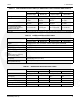
60 Hz 50 Hz
Propane Vapor Natural Gas Propane Vapor Natural Gas
De-rating Guidelines: Maximum wattage or maximum current are subject to and limited by such factors as fuel Btu
content, ambient temperature, altitude, engine power and condition, etc. Full rated power is available at 60 °F (15.5
°C) at sea level. De-rate 3.5% for each 1000 ft (304.8 m) above sea level and 3% for each 10 °F (5.5 °C) increase in
ambient temperature above 60 °F (15.5 °C).This generator is rated in accordance with UL 2200 (Stationary Engine
Generator Assemblies) or CSA C22.2 No. 100-04 (Motors and Generators). The maximum continuous current values
that are listed on the generator set nameplate and specification tables occur at the lower limit of acceptable voltage.
Maximum current occurs at 108 and 216 volts, 10% below nominal voltage 120/240. The voltage set point of this
generator set can be adjusted from the operator panel if desired. Refer to the Operator manual procedure To Adjust
the Output Voltage.
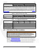
TABLE 8. CONTROL SPECIFICATIONS TABLE
60 Hz 50 Hz
Propane Vapor Natural Gas Propane Vapor Natural Gas
Controller Integrated Microprocessor-Based Engine, Generator, Transfer Switch Controller
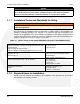
TABLE 9. DC SYSTEM SPECIFICATIONS TABLE
60 Hz 50 Hz
Propane Vapor Natural Gas Propane Vapor Natural Gas
DC System
Nominal Battery Voltage 12 Volts DC
Battery Group 26 R
Battery Type Maintenance Free
Minimum Cold Crank Amps 545
2.3 Information For After Installation
WARNING
Improper installation can result in severe personal injury, death and damage to
equipment. The installation must comply with all applicable building codes. It is
strongly recommended that the installer be properly trained and licensed to perform
electrical and mechanical equipment installations, however a person with the proper
knowledge and experience in installing electrical and mechanical equipment
installations may also install this genset.
Refer to the GSBB Specifications Sheet for specific information about the system and it's
components.
Refer to the Outline and System Drawings for specific information about the installation and
wiring connections.
See the Operator Manual (A029V089) for proper operation and maintenance instructions.
8 A029V088 (Issue 16)