
Product Manual

21A046S594 (Issue 19) Copyright © 2019 Cummins Inc.
3 Installation
3.1 Installation - Mounting
3.1.1 Introduction
Proper storage, installation, operation, and maintenance helps to increase the life of the transfer switch.
Installation is to be done only by licensed certified electricians.
WARNING
AC power within the cabinet presents a shock hazard that can cause severe personal injury or
death. Incorrect installation, service, or parts replacement can result in severe personal injury,
death, and/or equipment damage. All corrective service procedures must be done only by
technically trained and experienced personnel.
Each RA series transfer switch is factory wired and tested. Installation of the RA transfer switch includes
the following.
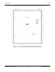
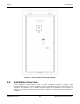
• Mounting a transfer switch cabinet
• Connection of all Utility, Generator, and Load cables (covered in Section 3.2)
• Connection of low voltage signal circuits (covered in Section 3.2.2)
RA Series transfer switches are only designed to be installed with the generator models identified
in Section 2.1. Installing this switch with any other generator model will void the warranty.
3.1.2 Equipment Inspection and Storage
Once you have received the transfer switch, inspect it for any damage. Check for damage to the
enclosure, the transfer switch, the control panel (if applicable), and the wiring harness.
Prior to installation, make sure the transfer switch is stored in a clean dry place, protected from dirt and
water. Provide ample air circulation and heat, if necessary, to prevent condensation from gathering on the
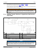
equipment. Be sure to adhere to the transfer switch storage and operating requirements listed below.
TABLE 2. TRANSFER SWITCH STORAGE AND OPERATING REQUIREMENTS
Model Storage Temperature
Operating Temperature
(Ambient)
Humidity
RA112N3,
RA212N3,
RA112S3, and
RA212S3
-22 °F to +158 °F
(-30 °C to +70 °C)
-4 °F to +140 °F
(-20 °C to +60 °C)
5% to 95%
(Non-Condensing)
RA412N3 and
RA412S3
-13 °F to +131 °F
(-25 °C to +55 °C)
-4 °F to +122 °F
(-20 °C to +50 °C)
Up to 90%
at 68 °F (20 °C)
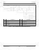
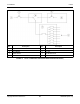
3.1.3 Location
The location of the transfer switch in the existing electrical circuit varies with the application and the type
of entrance switch. The location and wiring must comply with the contract drawings.
There must be a service disconnect in the commercial power line ahead of the transfer switch.