
Product Manual

5. Transfer Switch Service8-2019
59A046S594 (Issue 19) Copyright © 2019 Cummins Inc.
iv. Remove AC power to the automatic transfer switch.
b. Remove the transfer switch cabinet door panel.
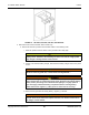
c. Remove the following:
i. The plastic barrier covering access to the mechanical lugs
ii. The two M10X1.25 bolts and washers securing the mechanical lugs to the circuit breaker
iii. The two 3/8-16 bolts and washers securing the busbars to the breaker
iv. The four #10-32 bolts, washers, and nuts securing the breaker to the breaker mounting
bracket
v. The circuit breaker
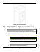
d. Use the hardware removed in the previous step to install the replacement circuit breaker.
i. Secure the circuit breaker to the circuit breaker mounting bracket with the four #10-32
bolts. Torque to 17 in-lb (2 Nm).
ii. Secure the busbars to the breaker with the two 3/8-16 bolts. Torque to 159 in-lb (18 Nm).
iii. Secure the mechanical lugs to the circuit breaker with two M10X1.25 bolts. Torque to 150
in-lb (17 Nm).
iv. Secure the plastic barrier to the circuit breaker.
v. Secure the inner and outer door panels to the cabinet before restoring power. Torque six
M6 bolts to 48.7 in-lb (5.5 Nm). Be sure to properly align the bolts to avoid cross-
threading.
e. Restore power.
i. Reconnect the generator set starting battery, negative (–) lead first.
ii. If there is an external battery charger, reconnect the battery charger to its AC power
source.
iii. Restore AC power to the automatic transfer switch.
iv. Move the operation selector switch on the generator set to the Remote (or Auto) position.