
Product Manual

4. Installation 2-2017
44 A055H194 (Issue 3)Copyright © 2017 Cummins Inc.
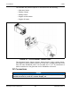
Install the transfer switch in accordance with the specific transfer switch owner
or operator manual.
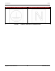
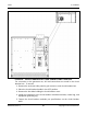
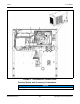
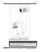
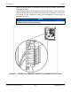
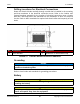
The following image is an example that shows the location of the connectors
in the generator set where the ATS DC control wires terminate. This is also
the location of the connectors where load management control wires (if
applicable) terminate.
NOTICE
Class 1 wiring methods should be used for connecting the generator
set and transfer switch signal wiring.
FIGURE 12. EXAMPLE OF TRANSFER SWITCH DC CONNECTIONS LOCATION