
Product Manual


Appendix A. Diesel Fuel Piping 2-2017
70 A055H194 (Issue 3)Copyright © 2017 Cummins Inc.
A.0 Diesel Fuel Piping Requirements
• Diesel fuel lines should be constructed from black iron pipe. Cast iron
and aluminum pipe and fittings must not be used because they are
porous and can leak fuel. Galvanized fuel lines, fittings, and tanks
must not be used because the galvanized coating is attacked by the
sulfuric acid that forms when the sulfur in the fuel combines with tank
condensate, resulting in debris that can clog fuel pumps and filters.
Copper lines should not be used because fuel polymerizes (thickens)
in copper tubing during long periods of disuse and can clog fuel
injectors. Also, copper lines are less rugged than black iron, and thus
more susceptible to damage.
NOTICE
Never use galvanized or copper fuel lines, fittings or fuel tanks.
Condensation in the tank and lines combines with the sulfur in
the diesel fuel to produce sulfuric acid. The molecular structure
of the copper or galvanized lines or tanks reacts with the acid
and contaminates the fuel.
• Approved flexible fuel hose must be used for connections at the
engine to take up generator set movement and vibration.
• Piping from a day tank to the engine should run “downhill" all the way
from the tank to the engine, with no overhead loops that can allow air
to be entrained in the system.
• Fuel system piping should be properly supported to prevent vibration
and breakage due to vibration. The piping should not run close to
heating pipes, electrical wiring, or engine exhaust system
components. The piping system design should include valves at
appropriate locations to allow isolation of system components for
repair without draining the entire fuel system.
• Piping systems should be regularly inspected for leaks and general
condition. The piping system should be flushed before operation of
the engine to remove dirt and other impurities that could damage the
engine. Use of plugged “T" connections rather than elbows allows for
easier cleaning of the piping system.
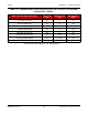
• The engine manufacturer's data indicates the maximum fuel inlet and
return restrictions, the maximum fuel flow, supply and return, and the
fuel consumption. The table below indicates minimum hose and pipe
sizes for connections to a supply tank or day tank when it is within 50
feet (15 meters) of the set and at approximately the same elevation.
Hose and pipe size should be based on the maximum fuel flow rather
than on the fuel consumption. It is highly recommended that the fuel inlet
and return restrictions be checked before the generator set is placed in
service.