Registered Office Cummins Ltd. 49 - 51 Gresham Road, Staines, Middlesex TW18 2BD, England Registration 573951 England Cummins Customer Assistance Center 1-800-DIESELSTM (1-800-343-7357) APPLICABLE ONLY IN U.S.A. AND CANADA Copyright© 2013 Cummins Inc. Bulletin 4021389 Printed in U.S.A. 17-OCTOBER-2013 335595_Cummins_Cover.indd 1 Operation and Maintenance Manual Industrial B3.9, B4.5, and B5.9 Series Engines Cummins Inc. Box 3005 Columbus, Indiana, U.S.A.
Operation and Maintenance Manual Industrial B3.9, B4.5, and B5.9 Series Engines Copyright© 2013 Cummins Inc.
Foreword This manual contains information for the correct operation and maintenance of your Cummins engine. It also includes important safety information, engine and systems specifications, troubleshooting guidelines, and listings of Cummins Authorized Repair Locations and component manufacturers. Read and follow all safety instructions. Refer to the WARNING in the General Safety Instructions in Section i Introduction. Keep this manual with the equipment.
Table of Contents Section Introduction ........................................................................................................................................................ i Engine and System Identification .................................................................................................................... E Operating Instructions ......................................................................................................................................
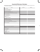
Important Reference Numbers Fill in the part name and number in the blank spaces provided below. This will give you a reference whenever service or maintenance is required.
B3.9, B4.5, B5.9 Industrial Section i - Introduction Page i-a Section i - Introduction Section Contents Page About the Manual .........................................................................................................................................................i-2 General Information.....................................................................................................................................................i-2 Acronyms and Abbreviations ............................
B3.9, B4.5, B5.
B3.9, B4.5, B5.9 Industrial Section i - Introduction To the Owner and Operator Page i-1 To the Owner and Operator General Information Preventive maintenance is the easiest and least expensive type of maintenance. Follow the maintenance schedule recommendations outlined in Maintenance Guidelines (Section 2). Keep records of regularly scheduled maintenance. Use the correct fuel, lubricating oil, and coolant in your engine as specified in Maintenance Specifications (Section V).
About the Manual Page i-2 B3.9, B4.5, B5.9 Industrial Section i - Introduction About the Manual General Information This manual contains information needed to correctly operate and maintain your engine as recommended by Cummins Inc. For additional service literature and ordering locations, refer to Service Literature (Section L). This manual does not cover vehicle, vessel, or equipment maintenance procedures.
B3.9, B4.5, B5.9 Industrial Section i - Introduction How to Use the Manual Page i-3 How to Use the Manual General Information This manual is organized according to intervals at which maintenance on your engine is to be performed. A maintenance schedule, that states the required intervals and maintenance checks, is located in Maintenance Guidelines (Section 2). Locate the interval at which you are performing maintenance; then follow the steps given in that section for all the procedures to be performed.
Symbols Page i-4 B3.9, B4.5, B5.9 Industrial Section i - Introduction Symbols General Information The following symbols have been used in this manual to help communicate the intent of the instructions.
B3.9, B4.5, B5.9 Industrial Section i - Introduction Illustrations General Information Some of the illustrations throughout this manual are generic and will not look exactly like the engine or parts used in your application. The illustrations can contain symbols to indicate an action required and an acceptable or not acceptable condition. The illustrations are intended to show repair or replacement procedures. The procedure will be the same for all applications, although the illustration can differ.
General Safety Instructions Page i-6 B3.9, B4.5, B5.9 Industrial Section i - Introduction General Safety Instructions Important Safety Notice WARNING Improper practices, carelessness, or ignoring the warnings can cause burns, cuts, mutilation, asphyxiation or other personal injury or death. Read and understand all of the safety precautions and warnings before performing any repair. This list contains the general safety precautions that must be followed to provide personal safety.
B3.9, B4.5, B5.9 Industrial Section i - Introduction General Safety Instructions Page i-7 • Some state and federal agencies in the United States of America have determined that used engine oil can be carcinogenic and can cause reproductive toxicity. Avoid inhalation of vapors, ingestion, and prolonged contact with used engine oil. • Do not connect the jumper starting or battery charging cables to any ignition or governor control wiring. This can cause electrical damage to the ignition or governor.
General Repair Instructions Page i-8 B3.9, B4.5, B5.9 Industrial Section i - Introduction General Repair Instructions General Information This engine or system incorporates the latest technology at the time it was manufactured; yet, it is designed to be repaired using normal repair practices performed to quality standards. WARNING Cummins Inc. does not recommend or authorize any modifications or repairs to components except for those detailed in Cummins Service Information.
B3.9, B4.5, B5.9 Industrial Section i - Introduction General Repair Instructions Page i-9 • Perform the inspections specified in the procedures • Replace all components or assemblies which are damaged or worn beyond the specifications • Use genuine Cummins new or ReCon® service parts and assemblies - The assembly instructions have been written to use again as many components and assemblies as possible.
General Cleaning Instructions Page i-10 B3.9, B4.5, B5.9 Industrial Section i - Introduction General Cleaning Instructions Definition of Clean Parts must be free of debris that can contaminate any engine system. This does not necessarily mean they have to appear as new. Sanding gasket surfaces until the factory machining marks are disturbed adds no value and is often harmful to forming a seal. It is important to maintain surface finish and flatness tolerances to form a quality sealing surface.
B3.9, B4.5, B5.9 Industrial Section i - Introduction General Cleaning Instructions Page i-11 abrade the other part until contact is no longer being made between the two parts. If the damage sufficiently degrades the oil film, the two parts will come into contact resulting in early wear-out or failure from lack of effective lubrication. Abrasive particles can fly about during cleaning it is very important to block these particles from entering the engine as much as possible.
General Cleaning Instructions Page i-12 B3.9, B4.5, B5.9 Industrial Section i - Introduction pressure water or steam clean the parts before putting them in the cleaning tank. Removing the heaviest dirt before placing in the tank will allow the cleaner to work more effectively and the cleaning agent will last longer. Rinse all the parts in hot water after cleaning. Dry completely with compressed air. Blow the rinse water from all the capscrew holes and the oil drillings.
B3.9, B4.5, B5.9 Industrial Section i - Introduction General Cleaning Instructions Page i-13 2 Operating Pressure — 270 kPa (40 psi) for piston cleaning. Pressure should not cause beads to break. 3 Steam clean or wash the parts with solvent to remove all of the foreign material and plastic beads after cleaning. Rinse with hot water. Dry with compressed air. CAUTION The bead blasting operation must not disturb the metal surface.
General Cleaning Instructions Page i-14 B3.9, B4.5, B5.9 Industrial Section i - Introduction is 76 microns [0.003 in] in diameter. One micron measures 0.001 mm [0.00004 in.]. The contaminants being filtered out are smaller than can be seen with the human eye, a magnifying glass, or a low powered microscope. The tools used for fuel system troubleshooting and repair are to be cleaned regularly to avoid contamination.
B3.9, B4.5, B5.9 Industrial Section i - Introduction Acronyms and Abbreviations Page i-15 Acronyms and Abbreviations General Information The following list contains some of the acronyms and abbreviations used in this manual. ANSI API ASTM ATDC BTU BTDC °C CAN CO CCA CARB C.I.B. C.I.D.
Acronyms and Abbreviations Page i-16 NOx NG O2 OBD OEM OSHA PID ppm psi PTO REPTO RGT rpm SAE SCA SCR STC SID TDC VDC VGT VS VSS B3.9, B4.5, B5.
B3.9, B4.5, B5.9 Industrial Section E - Engine and System Identification Page E-a Section E - Engine and System Identification Section Contents Page Cummins® Service Engine Model Product Identification ....................................................................................E-25 General Information..................................................................................................................................................E-25 Engine Diagrams .................................
Page E-b B3.9, B4.5, B5.
B3.9, B4.5, B5.9 Industrial Section E - Engine and System Identification Engine Identification Page E-1 Engine Identification Engine Dataplate B3.9, B5.9, and B4.5 Engines The engine dataplate shows specific facts about your engine. The engine serial number and Control Parts List provide information for ordering parts and for service. The engine dataplate must not be changed unless approved by Cummins Inc. B4.5 RGT Engines The engine dataplate shows specific facts about your engine.
Engine Identification Page E-2 B3.9, B4.5, B5.9 Industrial Section E - Engine and System Identification NOTE: If the engine dataplate (1) is not readable, the engine serial number (2) can be identified on the engine block above the oil cooler. Cummins® Engine Nomenclature B5.9 The model name provides the following engine data: B = Engine series 5.9 = Displacement in liters. B3.9 The model name provides the following engine data: B = Engine series 3.9 = Displacement in liters.
B3.9, B4.5, B5.9 Industrial Section E - Engine and System Identification The model name for engines in industrial applications provides the data shown below For example: 4BTAA-3.9 4 = Number of cylinders B = Engine series T = Turbocharged AA = Charge air cooled 3.9 = Displacement in liters. NOTE: The suffix RGT refers to “Rear Gear Train” engines. Fuel Injection Pump Dataplate Bosch® Rotary The injection pump dataplate for the Bosch® VE pump is located on the side of the injection pump.
Engine Diagrams Page E-4 B3.9, B4.5, B5.9 Industrial Section E - Engine and System Identification Engine Diagrams Engine Views The following illustrations show the locations of the major external engine components, filters, and other service and maintenance points. Some external components will be at different locations for different engine models. NOTE: The illustrations are only a reference to show a typical engine.
B3.9, B4.5, B5.9 Industrial Section E - Engine and System Identification Engine Diagrams Page E-5 Engine Diagrams Engine Views Front View - B3.9 Industrial 1. 2. 3. 4. 5. 6. 7. 8. 9. 10. 11. 12. 13. 14. Turbocharger air outlet Lubricating oil fill Engine air inlet Fuel pump drive cover Front gear cover Accessory drive cover (optional) Fan drive belt Front Pulley Water pump Automatic belt tensioner Water inlet Alternator Fan pulley Turbocharger air inlet.
Engine Diagrams Page E-6 B3.9, B4.5, B5.9 Industrial Section E - Engine and System Identification Engine Diagrams Engine Views Left Side View - B3.9 Industrial 1. 2. 3. 4. 5. 6. 7. 8. 9. 10. 11. 12. 13.
B3.9, B4.5, B5.9 Industrial Section E - Engine and System Identification Engine Diagrams Page E-7 Engine Diagrams Engine Views Rear View - B3.9 Industrial 1. 2. 3. 4. 5. Rear engine lifting bracket Turbocharger exhaust outlet Flexplate mounting holes Flywheel housing Flywheel/flexplate.
Engine Diagrams Page E-8 B3.9, B4.5, B5.9 Industrial Section E - Engine and System Identification Engine Diagrams Engine Views Right Side View - B3.9 Industrial 1. 2. 3. 4. 5. 6. 7. 8. 9. 10. 11. 12. Fuel injection nozzles Turbocharger wastegate actuator Lubricating oil fill Front engine lifting bracket Water outlet Lubricating oil filter Water inlet Lubricating oil cooler Lubricating oil drain Provision for lubricating oil immersion heater Starter motor and solenoid Provision for coolant heater.
B3.9, B4.5, B5.9 Industrial Section E - Engine and System Identification Engine Diagrams Page E-9 Engine Diagrams Engine Views Top View - B3.9 Industrial 1. 2. 3. 4. 5. Water outlet Turbocharger Exhaust manifold Magnetic pickup location (3/4-16 UNF) Engine air inlet.
Engine Diagrams Page E-10 B3.9, B4.5, B5.9 Industrial Section E - Engine and System Identification Engine Diagrams Engine Views Front View - B4.5 Industrial 1. 2. 3. 4. 5. 6. 7. 8. 9. 10. 11. 12. 13. 14. Turbocharger air outlet Lubricating oil fill Engine air inlet Fuel pump drive cover Front gear cover Accessory drive cover (optional) Fan drive belt Front Pulley Water pump Automatic belt tensioner Water inlet Alternator Fan pulley Turbocharger air inlet.
B3.9, B4.5, B5.9 Industrial Section E - Engine and System Identification Engine Diagrams Page E-11 Engine Diagrams Engine Views Left Side View - B4.5 Industrial 1. 2. 3. 4. 5. 6. 7. 8. 9. 10. 11. 12. 13.
Engine Diagrams Page E-12 B3.9, B4.5, B5.9 Industrial Section E - Engine and System Identification Engine Diagrams Engine Views Rear View - B4.5 Industrial 1. 2. 3. 4. 5. Rear engine lifting bracket Turbocharger exhaust outlet Flexplate mounting holes Flywheel housing Flywheel/flexplate.
B3.9, B4.5, B5.9 Industrial Section E - Engine and System Identification Engine Diagrams Page E-13 Engine Diagrams Engine Views Right Side View - B4.5 Industrial 1. 2. 3. 4. 5. 6. 7. 8. 9. 10. 11. 12. Fuel injection nozzles Turbocharger wastegate actuator Lubricating oil fill Front engine lifting bracket Water outlet Lubricating oil filter Water inlet Lubricating oil cooler Lubricating oil drain Provision for lubricating oil immersion heater Starter motor and solenoid Provision for coolant heater.
Engine Diagrams Page E-14 B3.9, B4.5, B5.9 Industrial Section E - Engine and System Identification Engine Diagrams Engine Views Top View - B4.5 Industrial 1. 2. 3. 4. 5. Water outlet Turbocharger Exhaust manifold Magnetic pickup location (3/4-16 UNF) Engine air inlet.
B3.9, B4.5, B5.9 Industrial Section E - Engine and System Identification Engine Diagrams Page E-15 Engine Diagrams Engine Views Front View - B4.5 RGT 1. 2. 3. 4. 5. 6. 7. 8. 9. Engine air inlet Lubricating oil dipstick Fan drive belt Front pulley Water pump Automatic belt tensioner Alternator Fan pulley Lubricating oil fill.
Engine Diagrams Page E-16 B3.9, B4.5, B5.9 Industrial Section E - Engine and System Identification Engine Diagrams Engine Views Left Side View - B4.5 RGT 1. 2. 3. 4. 5. 6. 7. 8. 9. 10. 11. 12. 13. 14.
B3.9, B4.5, B5.9 Industrial Section E - Engine and System Identification Engine Diagrams Page E-17 Engine Diagrams Engine Views Rear View - B4.5 RGT 1. 2. 3. 4. 5. 6. 7. 8. 9. 10. Rear engine lifting bracket Fuel return and fuel drain connection Inline fuel filter Fuel Inlet connection Exhaust outlet Flexplate mounting holes Flywheel/flexplate Flywheel housing Rear gear train housing Crankcase breather tube.
Engine Diagrams Page E-18 B3.9, B4.5, B5.9 Industrial Section E - Engine and System Identification Engine Diagrams Engine Views Right Side View - B4.5 RGT 1. 2. 3. 4. 5. 6. 7. 8. 9. Lubricating oil fill Front engine lifting bracket Water outlet Lubricating oil filter Water inlet Lubricating oil cooler Lubricating oil drain Starter motor and solenoid Provision for coolant heater.
B3.9, B4.5, B5.9 Industrial Section E - Engine and System Identification Engine Diagrams Page E-19 Engine Diagrams Engine Views Top View - B4.5 RGT 1. 2. 3. 4. Exhaust manifold Engine air inlet Magnetic pickup location (3/4-16 UNF).
Engine Diagrams Page E-20 B3.9, B4.5, B5.9 Industrial Section E - Engine and System Identification Engine Diagrams Engine Views Front View - B5.9 Industrial 1. 2. 3. 4. 5. 6. 7. 8. 9. 10. 11. 12. 13. 14. Turbocharger air outlet Lubricating oil fill Engine air inlet Fuel pump drive cover Front gear cover Accessory drive cover (optional) Fan drive belt Vibration damper Water pump Automatic belt tensioner Water inlet Alternator Fan pulley Turbocharger air inlet.
B3.9, B4.5, B5.9 Industrial Section E - Engine and System Identification Engine Diagrams Page E-21 Engine Diagrams Engine Views Left Side View - B5.9 Industrial 1. 2. 3. 4. 5. 6. 7. 8. 9. 10. 11. 12. 13.
Engine Diagrams Page E-22 B3.9, B4.5, B5.9 Industrial Section E - Engine and System Identification Engine Diagrams Engine Views Rear View - B5.9 Industrial 1. 2. 3. 4. 5. Rear engine lifting bracket Turbocharger exhaust outlet Flexplate mounting holes Flywheel housing Flywheel/flexplate.
B3.9, B4.5, B5.9 Industrial Section E - Engine and System Identification Engine Diagrams Page E-23 Engine Diagrams Engine Views Right Side View - B5.9 Industrial 1. 2. 3. 4. 5. 6. 7. 8. 9. 10. 11. 12. Fuel injection nozzles Turbocharger wastegate actuator Lubricating oil fill Front engine lifting bracket Water outlet Lubricating oil filter Water inlet Lubricating oil cooler Provision for coolant heater Lubricating oil drain Provision for lubricating oil immersion heater Starter motor and solenoid.
Engine Diagrams Page E-24 B3.9, B4.5, B5.9 Industrial Section E - Engine and System Identification Engine Diagrams Engine Views Top View - B5.9 Industrial 1. 2. 3. 4. 5. Water outlet Turbocharger Exhaust manifold Magnetic pickup location (3/4-16 UNF) Engine air inlet.
B3.9, B4.5, B5.9 Industrial Section E - Engine and System Identification Cummins® Service Engine Product Identification Cummins® Service Engine Model Product Identification Page E-25 Model General Information The Cummins® Service Engine Model Nomenclature procedure describes how engines are identified within Cummins service organization. This method was introduced for models after and including manufacture year 2007.
Cummins® Service Engine Model Product Identification Page E-26 B3.9, B4.5, B5.9 Industrial Section E - Engine and System Identification The control system is identified with the letters "CM" followed by the control system model number. The technology identifier after the control system designates the prevailing technology used with the engine. (See table in this procedure for letter designations.
B3.9, B4.5, B5.
Cummins® Service Engine Model Product Identification Page E-28 B3.9, B4.5, B5.
B3.9, B4.5, B5.9 Industrial Section 1 - Operating Instructions Page 1-a Section 1 - Operating Instructions Section Contents Page Cold Weather Starting ................................................................................................................................................1-5 Ether Starting Aids......................................................................................................................................................1-6 Industrial Applications...............
B3.9, B4.5, B5.
B3.9, B4.5, B5.9 Industrial Section 1 - Operating Instructions Operating Instructions - Overview Page 1-1 Operating Instructions - Overview General Information Correct care of your engine will result in longer life, better performance, and more economical operation. Follow the daily maintenance checks Maintenance Guidelines (Section 2). listed in The new Cummins® engine associated with this manual does not require a "break-in" procedure.
Normal Starting Procedure Page 1-2 B3.9, B4.5, B5.9 Industrial Section 1 - Operating Instructions WARNING Do not operate a diesel engine where there are or can BE COMBUSTIBLE vapors. These vapors can be sucked through the air intake system and cause engine acceleration and over speeding that can result in a fire, an explosion, and extensive property damage.
B3.9, B4.5, B5.9 Industrial Section 1 - Operating Instructions CAUTION The engine must have adequate oil pressure within 15 seconds after starting. If the WARNING lamp indicating low oil pressure has not gone out or there is no oil pressure indicated on a gauge within 15 seconds, shut off the engine immediately to avoid engine damage. The low oil pressure troubleshooting procedure is located in Troubleshooting Symptoms(Section TS). Idle the engine 3 to 5 minutes before operating with a load.
Normal Starting Procedure Page 1-4 B3.9, B4.5, B5.9 Industrial Section 1 - Operating Instructions Jump Starting WARNING Batteries can emit explosive gases. To avoid personal injury, always ventilate the compartment before servicing the batteries. To avoid arcing, remove the negative (-) battery cable first and attach the negative(-) battery cable last.
B3.9, B4.5, B5.9 Industrial Section 1 - Operating Instructions Cold Weather Starting With Flame Start System WARNING Do not use starting fluids with this engine. This engine is equipped with a flame start system; use of starting fluid can cause an explosion, fire, personal injury, severe damage to the engine and property damage. The only recommended cold weather starting aids for industrial applications with grid a flame start system, are engine coolant preheaters and oil pan immersion heaters.
Cold Weather Starting Page 1-6 B3.9, B4.5, B5.9 Industrial Section 1 - Operating Instructions In cold weather, the WAIT-TO-START lamp will stay on longer. If ambient temperature is below 16° C [60° F], fully depress the throttle after engaging the stater. Full throttle on the VE pump makes sure there is sufficient start fuel delivery and helps keep the engine operating once started. The in-line pumps with RQV and RQV-K governors require full throttle position and hold the rack in the start fuel position.
B3.9, B4.5, B5.9 Industrial Section 1 - Operating Instructions Starting Procedure After Extended Shutdown or Oil Change General Information Complete the following steps after each oil change, or after the engine has been shut down for more than 30 days to make sure the engine receives the correct oil flow through the lubricating oil system. 1. Disconnect the electrical wire from the fuel pump solenoid. 2.
Engine Operating Range Page 1-8 B3.9, B4.5, B5.9 Industrial Section 1 - Operating Instructions Winterfronts and Shutters Winterfronts and shutters can be used on a vehicle or equipment to reduce air flow through the radiator core into the engine compartment. This can reduce the time required to warm the engine and help maintain the engine coolant temperature. The engine coolant temperature specifications are in the Maintenance Specification (Section V).
B3.9, B4.5, B5.9 Industrial Section 1 - Operating Instructions Electromagnetic Interference (EMI) Page 1-9 Engine Shutdown General Information Allow the engine to idle 3 to 5 minutes before shutting it off after a full-load operation. This allows adequate cool down of pistons, cylinders, bearings, and turbocharger components.
Electromagnetic Interference (EMI) Page 1-10 B3.9, B4.5, B5.
B3.9, B4.5, B5.9 Industrial Section 2 - Maintenance Guidelines Page 2-a Section 2 - Maintenance Guidelines Section Contents Page Maintenance Guidelines - Overview .........................................................................................................................2-1 General Information....................................................................................................................................................2-1 Maintenance Record Form ...........................
B3.9, B4.5, B5.
B3.9, B4.5, B5.9 Industrial Section 2 - Maintenance Guidelines Maintenance Guidelines - Overview Page 2-1 Maintenance Guidelines - Overview General Information Cummins Inc. recommends that the system be maintained according to the Maintenance Schedule in this section. If the system is operating in ambient temperatures below -18°C [0°F] or above 38°C [100°F], perform maintenance at shorter intervals.
Tool Requirements Page 2-2 B3.9, B4.5, B5.9 Industrial Section 2 - Maintenance Guidelines Tool Requirements General Information Most of the maintenance operations described in this manual can be performed with common hand tools (metric and S.A.E. wrenches, sockets, and screwdrivers).
B3.9, B4.5, B5.9 Industrial Section 2 - Maintenance Guidelines Maintenance Schedule Page 2-3 Maintenance Schedule General Information For your convenience, listed below are the section numbers that contain specific instructions for performing the maintenance checks. Perform maintenance at whichever interval occurs first. At each scheduled maintenance interval, perform all previous maintenance checks that are due for scheduled maintenance. Maintenance Procedures at Daily Interval(4) .......................
Maintenance Schedule Page 2-4 B3.9, B4.5, B5.9 Industrial Section 2 - Maintenance Guidelines 3 Antifreeze check interval is every oil change or 500 hours or 6 months, whichever occurs first. The operator must use a heavy-duty year-round antifreeze that meets the chemical composition of ASTM D6210. The antifreeze change interval is 2 years, 2000 hours, or whichever occurs first. Antifreeze is essential for freeze, overheat, and corrosion protection.
B3.9, B4.5, B5.9 Industrial Section 2 - Maintenance Guidelines Maintenance Record Form Page 2-5 Maintenance Record Form Maintenance Data Maintenance Record Engine Model: Equipment Name/Number: Engine Serial No.
Maintenance Record Form Page 2-6 B3.9, B4.5, B5.
B3.9, B4.5, B5.9 Industrial Section 3 - Maintenance Procedures at Daily Interval Page 3-a Section 3 - Maintenance Procedures at Daily Interval Section Contents Page Air Intake Piping ..........................................................................................................................................................3-2 Maintenance Check....................................................................................................................................................
Page 3-b B3.9, B4.5, B5.
B3.9, B4.5, B5.9 Industrial Section 3 - Maintenance Procedures at Daily Interval Daily Maintenance Procedures - Overview Page 3-1 Daily Maintenance Procedures - Overview General Information Preventative maintenance begins with day-to-day awareness of the system. Before starting the system, check the appropriate fluid levels. Look for: • Leaks • Loose or damaged parts • Worn or damaged belts • Worn or damage low and high voltage harnesses • Any change in system appearance.
Fan, Cooling Page 3-2 B3.9, B4.5, B5.9 Industrial Section 3 - Maintenance Procedures at Daily Interval Air Intake Piping Maintenance Check Inspect the intake piping daily for wear points and damage to piping, loose clamps, and punctures that can damage the engine. Replace damaged pipes and tighten loose clamps, as necessary, to prevent the air system from leaking. Torque Value: 8 N•m [ 71 in-lb ] Check for corrosion under the clamps and hoses of the intake system piping.
B3.9, B4.5, B5.9 Industrial Section 3 - Maintenance Procedures at Daily Interval WARNING Do not straighten a bent fan blade or continue to use a damaged fan. A bent or damaged fan blade can fail during operation and cause personal injury or property damage. Replace original equipment fan that is damaged with a fan of the identical part number. Cummins Inc. must approve any other fan changes to be covered under warranty. Refer to the vehicle or equipment manufacturer's specifications for capscrew torque.
Coolant Level Page 3-4 B3.9, B4.5, B5.9 Industrial Section 3 - Maintenance Procedures at Daily Interval Visually inspect the tube for cracks or damage. If damage is found, replace the crankcase breather tube. Contact your Cummins Authorized Repair Location. Coolant Level Maintenance Check WARNING Do not remove a pressure cap from a hot engine. Wait until the coolant temperature is below 50°C [120°F] before removing the pressure cap. Heated coolant spray or steam can cause personal injury.
B3.9, B4.5, B5.9 Industrial Section 3 - Maintenance Procedures at Daily Interval Drive Belts Maintenance Check Poly-Vee Belt CAUTION Make sure that the engine is switched off and any starting mechanisms are isolated before any inspections are made. Daily belt inspections can be carried out through an appropriate aperture. Do not remove any guards. Inspect the belts daily. Check the belt for intersecting cracks. Traverse (across the belt width) cracks are acceptable.
Fuel-Water Separator Page 3-6 B3.9, B4.5, B5.9 Industrial Section 3 - Maintenance Procedures at Daily Interval Measure the belt tension in the center span of the pulleys. Refer to the Belt Tension Chart in Section V for the correct gauge and tension value for the belt width used. An alternate method (deflection method) can be used to check belt tension by applying 110 N [25 lbf] force between the pulleys on v-belts.
B3.9, B4.5, B5.9 Industrial Section 3 - Maintenance Procedures at Daily Interval Spin-on Type Shut off the engine. Use your hand to open the drain valve. Turn the valve counterclockwise approximately 3½ turns until the valve drops down 25.4mm [1 in] and draining occurs. Drain the filter sump until clear fuel is visible. CAUTION When closing the drain valve, do not overtighten the valve. Overtightening can damage the threads. To close the valve, lift the valve and turn clockwise until it is hand-tight.
Lubricating Oil Level Page 3-8 B3.9, B4.5, B5.
B3.9, B4.5, B5.9 Industrial Section 4 - Maintenance Procedures at 250 Hours or 3 Months Page 4-a Section 4 - Maintenance Procedures at 250 Hours or 3 Months Section Contents Page Air Cleaner Restriction ...............................................................................................................................................4-1 Maintenance Check...............................................................................................................................................
Page 4-b B3.9, B4.5, B5.
B3.9, B4.5, B5.9 Industrial Section 4 - Maintenance Procedures at 250 Hours or 3 Months Maintenance Procedures - Overview General Information All maintenance checks and inspections listed in previous maintenance intervals must also be performed at this time, in addition to those listed under this maintenance interval. Air Cleaner Restriction Maintenance Check Mechanical Indicator CAUTION Never operate the engine without an air cleaner.
Charge-Air Cooler Page 4-2 B3.9, B4.5, B5.9 Industrial Section 4 - Maintenance Procedures at 250 Hours or 3 Months Industrial Gas Mechanical Indicator A mechanical restriction indicator is available to indicate excessive air restriction through a dry-type air cleaner. This instrument is mounted in the air cleaner outlet. The red flag (1) in the window gradually rises as the cartridge loads with dirt. When air restriction is indicated the air filter must be replaced.
B3.9, B4.5, B5.9 Industrial Section 4 - Maintenance Procedures at 250 Hours or 3 Months Charge-Air Piping Maintenance Check Inspect the charge-air piping and hoses for leaks, holes, cracks, or loose connections. Tighten the hose clamps if necessary. Refer to the vehicle or equipment manufacturer's specifications for the correct torque value. Fuel Pump Maintenance Check Inspect the fuel injection pump mounting nuts, including the tail support bracket, for loose or damaged hardware.
Radiator Pressure Cap Page 4-4 B3.9, B4.5, B5.9 Industrial Section 4 - Maintenance Procedures at 250 Hours or 3 Months The illustration shown is the second of two options available for the closed-crankcase ventilation system. Radiator Pressure Cap General Information Pressure Caps The system is designed to use a pressure cap to prevent boiling of the coolant.
B3.9, B4.5, B5.9 Industrial Section 4 - Maintenance Procedures at 250 Hours or 3 Months Air in the coolant can result in loss of coolant from the overflow when the aerated coolant is hot. The heated air expands, increasing the pressure in the system, causing the cap to open. Similarly, coolant can be displaced through the overflow if the head gasket leaks compression gases to the coolant system.
Radiator Pressure Cap Page 4-6 B3.9, B4.5, B5.9 Industrial Section 4 - Maintenance Procedures at 250 Hours or 3 Months Pressure-test the radiator cap. The pressure cap must seal within the value stated on the cap, or it must be replaced. NOTE: An incorrect or malfunctioning cap can result in loss of coolant and the engine running hot.
B3.9, B4.5, B5.9 Industrial Section 5 - Maintenance Procedures at 500 Hours or 6 Months Page 5-a Section 5 - Maintenance Procedures at 500 Hours or 6 Months Section Contents Page Engine Coolant Antifreeze .........................................................................................................................................5-1 Maintenance Check...................................................................................................................................................
Page 5-b B3.9, B4.5, B5.
B3.9, B4.5, B5.9 Industrial Section 5 - Maintenance Procedures at 500 Hours or 6 Months Maintenance Procedures - Overview General Information All maintenance checks and inspections listed in previous maintenance intervals must also be performed at this time, in addition to those listed under this maintenance interval. Engine Coolant Antifreeze Maintenance Check CAUTION Overconcentration of antifreeze or use of high silicate antifreeze can cause damage to the engine. Check the antifreeze concentration.
Fuel Filter (Canister Type) Page 5-2 B3.9, B4.5, B5.9 Industrial Section 5 - Maintenance Procedures at 500 Hours or 6 Months Remove Clean all debris from around the canister lid. Remove the filter lid and filter element. A crescent wrench can be used if the lid can not be removed by hand. NOTE: Remove the filter element by twisting the element sideways from the filter lid. Install Install the new element in the canister lid, and place back in the canister by twisting clockwise.
B3.9, B4.5, B5.9 Industrial Section 5 - Maintenance Procedures at 500 Hours or 6 Months Open the bleed screw. Operate the hand lever until the fuel flowing from the fitting is free of air. Tighten the bleed screw. Torque Value: 9 N•m [ 80 in-lb ] Air and fuel can be vented from the illustrated vent locations on the Bosch® VE fuel injection pumps. Loosen the vent screw and operate the priming lever on the fuel transfer pump until the fuel injection pump is primed. Tighten the vent screw.
Fuel Filter (Spin-On Type) Page 5-4 B3.9, B4.5, B5.9 Industrial Section 5 - Maintenance Procedures at 500 Hours or 6 Months Fuel Filter (Spin-On Type) Preparatory Steps WARNING Batteries can emit explosive gases. To reduce the possibility of personal injury, always ventilate the compartment before servicing the batteries. To reduce the possibility of arcing, remove the negative (-) battery cable first and attach the negative (-) battery cable last. • Disconnect the batteries.
B3.9, B4.5, B5.9 Industrial Section 5 - Maintenance Procedures at 500 Hours or 6 Months Install WARNING Fuel is flammable. Keep all cigarettes, flames, pilot lights, arcing equipment, and switches out of the work area and areas sharing ventilation to reduce the possibility of severe personal injury or death when working on the fuel system. CAUTION When pre-filling the filter do not pour fuel down the center (clean side) of the filter. Pour clean fuel into the outer openings (dirty side) of the filter.
Fuel Filter (Spin-On Type) Page 5-6 B3.9, B4.5, B5.9 Industrial Section 5 - Maintenance Procedures at 500 Hours or 6 Months WARNING Batteries can emit explosive gases. To reduce the possibility of personal injury, always ventilate the compartment before servicing the batteries. To reduce the possibility of arcing, remove the negative (-) battery cable first and attach the negative (-) battery cable last. Connect the batteries.
B3.9, B4.5, B5.9 Industrial Section 5 - Maintenance Procedures at 500 Hours or 6 Months CAUTION It is necessary to turn the keyswitch to the ON position. Because the engine can start, be sure to follow all safety precautions. Use the normal engine starting procedure. CAUTION When using the starting motor to vent the system, do not engage the starter for more than 30 seconds, or starter damage will occur. Wait 2 minutes before starting the engine again.
Lubricating Oil and Filters Page 5-8 B3.9, B4.5, B5.9 Industrial Section 5 - Maintenance Procedures at 500 Hours or 6 Months Lubricating Oil and Filters Drain WARNING Some state and federal agencies have determined that used engine oil can be carcinogenic and cause reproductive toxicity. Avoid inhalation of vapors, ingestion, and prolonged contact with used engine oil. If not reused, dispose of in accordance with local environmental regulations.
B3.9, B4.5, B5.9 Industrial Section 5 - Maintenance Procedures at 500 Hours or 6 Months Install Use the correct oil filter. Refer to Procedure 018-004 (Cummins/Fleetguard® Filter Specifications) in Section V for oil filter part number(s). Fill the filter with clean lubricating oil before installation. Apply a light film of lubricating oil to the gasket sealing surface before installing the filter. CAUTION Mechanical overtightening of filter can distort the threads or damage the filter element seal.
Lubricating Oil and Filters Page 5-10 B3.9, B4.5, B5.9 Industrial Section 5 - Maintenance Procedures at 500 Hours or 6 Months Fill Use a high-quality 15W-40 multiviscosity lubricating oil, such as Valvoline® Premium Blue® or its equivalent, in Cummins engines. Choose the correct lubricating oil for your operating climate as outlined in Procedure 018-003 (Lubricating Oil Recommendations and Specifications) in Section V. Fill the engine with clean lubricating oil to the proper level.
B3.9, B4.5, B5.9 Industrial Section 6 - Maintenance Procedures at 1000 Hours or 1 Year Page 6-a Section 6 - Maintenance Procedures at 1000 Hours or 1 Year Section Contents Page Cooling Fan Belt Tensioner .......................................................................................................................................6-1 Maintenance Check....................................................................................................................................................
Page 6-b B3.9, B4.5, B5.
B3.9, B4.5, B5.9 Industrial Section 6 - Maintenance Procedures at 1000 Hours or 1 Year Maintenance Procedures - Overview General Information All maintenance checks and inspections listed in previous maintenance intervals must also be performed at this time, in addition to those listed under this maintenance interval. Cooling Fan Belt Tensioner Maintenance Check With the engine turned off, check that neither the top nor bottom tensioner arm stop is touching the cast boss on the tensioner body.
Fan Hub, Belt Driven Page 6-2 B3.9, B4.5, B5.9 Industrial Section 6 - Maintenance Procedures at 1000 Hours or 1 Year Inspect the tensioner for evidence of the pivoting tensioner arm contacting the stationary circular base. If there is evidence of these two areas touching, the pivot tube bushing has failed and the tensioner must be replaced. The worn tensioner that has play in it or a belt that “walks” off its pulley possibly indicates pulley misalignment. NOTE: Maximum pulley misalignment is 3 degrees.
B3.9, B4.5, B5.9 Industrial Section 6 - Maintenance Procedures at 1000 Hours or 1 Year Overhead Set Preparatory Steps WARNING Batteries can emit explosive gases. To reduce the possibility of personal injury, always ventilate the compartment before servicing the batteries. To reduce the possibility of arcing, remove the negative (-) battery cable first and attach the negative (-) battery cable last. • Disconnect the batteries. NOTE: The timing pin is used to accurately locate TDC for setting the overhead.
Overhead Set Page 6-4 B3.9, B4.5, B5.9 Industrial Section 6 - Maintenance Procedures at 1000 Hours or 1 Year CAUTION To reduce the possibility of engine or timing pin damage, you must disengage the timing pin after locating top dead center. Remove B3.9, B5.9, and B4.5 Engines Remove the capscrews, capscrew seals, rocker lever covers, and rocker lever cover gaskets. Adjust B3.9, B5.9, and B4.
B3.9, B4.5, B5.9 Industrial Section 6 - Maintenance Procedures at 1000 Hours or 1 Year CAUTION To reduce the possibility of engine or pin damage, be sure the timing pin is disengaged. Mark the vibration damper and rotate the crankshaft 360 degrees. Adjust the valves as indicated in the illustration. Torque Value: 24 N•m [ 18 ft-lb ] Set only valves indicated by the arrows (E = exhaust, I = intake). Do not set valves that are not indicated.
Overhead Set Page 6-6 B3.9, B4.5, B5.9 Industrial Section 6 - Maintenance Procedures at 1000 Hours or 1 Year Adjust the valves as indicated in the illustration. Set only the valves indicated by the arrows in the illustration (E = exhaust, I = intake). Do not set valves that are not indicated. Torque Value: 24 N•m [ 18 ft-lb ] Install B3.9, B5.9, and B4.5 Engines Install rocker lever covers with new rocker lever cover gaskets. Next install the capscrews with new capscrew seals.
B3.9, B4.5, B5.9 Industrial Section 7 - Maintenance Procedures at 2000 Hours or 2 Years Page 7-a Section 7 - Maintenance Procedures at 2000 Hours or 2 Years Section Contents Page Air Compressor Discharge Lines ..............................................................................................................................7-1 General Information....................................................................................................................................................
Page 7-b B3.9, B4.5, B5.
B3.9, B4.5, B5.9 Industrial Section 7 - Maintenance Procedures at 2000 Hours or 2 Years Maintenance Procedures - Overview General Information All maintenance checks and inspections listed in previous maintenance intervals must also be performed at this time, in addition to those listed under this maintenance interval. Air Compressor Discharge Lines General Information All air compressors have a small amount of lubricating oil carryover that lubricates the piston rings and moving parts.
Cooling System Page 7-2 B3.9, B4.5, B5.9 Industrial Section 7 - Maintenance Procedures at 2000 Hours or 2 Years Measure the total carbon deposit thickness inside the air discharge line as shown. If the total carbon deposit (X + X) exceeds 2 mm [1/16 in], clean and inspect the cylinder head, the valve assembly, and the discharge line. Replace if necessary. Contact the Cummins Authorized Repair Location for procedures.
B3.9, B4.5, B5.9 Industrial Section 7 - Maintenance Procedures at 2000 Hours or 2 Years WARNING Coolant is toxic. Keep away from children and pets. If not reused, dispose of in accordance with local environmental regulations. Drain the cooling system by opening the drain valve on the radiator and removing the plug in the bottom of the water inlet. A drain pan with a capacity of 19 liters [5 gal] will be adequate in most applications. Check for damaged hoses and loose or damaged hose clamps.
Cooling System Page 7-4 B3.9, B4.5, B5.9 Industrial Section 7 - Maintenance Procedures at 2000 Hours or 2 Years CAUTION The system must be filled properly to prevent air locks. During filling, air must be vented from the engine coolant passages. Wait 2 to 3 minutes to allow air to be vented then add mixture to bring the level to the top. For rear gear train engines, a dearation port next to the water outlet connection vents air to the top tank of the cooling system.
B3.9, B4.5, B5.9 Industrial Section 7 - Maintenance Procedures at 2000 Hours or 2 Years Fill the cooling system with clean water. NOTE: Be sure to vent the engine and aftercooler, if equipped, for complete filling. NOTE: Do not install the radiator cap. Operate the engine for 5 minutes with the coolant temperature above 80°C [176°F]. Shut the engine off, and drain the cooling system. NOTE: If the water being drained is still dirty, the system must be flushed again until the water is clean.
Vibration Damper, Rubber Page 7-6 B3.9, B4.5, B5.9 Industrial Section 7 - Maintenance Procedures at 2000 Hours or 2 Years CAUTION The system must be filled properly to prevent air locks. During filling, air must be vented from the engine coolant passages. Be sure to open the petcock on the aftercooler for aftercooled engines. Wait 2 to 3 minutes to allow air to be vented; then add mixture to bring the level to the top.
B3.9, B4.5, B5.9 Industrial Section 7 - Maintenance Procedures at 2000 Hours or 2 Years Inspect the rubber member for deterioration. If pieces of rubber are missing or if the elastic member is more than 3.18 mm [1/8 in] below the metal surface, replace the damper. Look for forward movement of the damper ring on the hub. Replace the vibration damper if any movement is detected. For vibration damper location, refer to Engine Diagrams in Engine Identification (Section E).
Vibration Damper, Viscous Page 7-8 B3.9, B4.5, B5.
B3.9, B4.5, B5.9 Industrial Section A - Adjustment, Repair, and Replacement Page A-a Section A - Adjustment, Repair, and Replacement Section Contents Page Air in Fuel ....................................................................................................................................................................A-1 General Information....................................................................................................................................................
Page A-b B3.9, B4.5, B5.
B3.9, B4.5, B5.9 Industrial Section A - Adjustment, Repair, and Replacement Air in Fuel General Information WARNING Fuel is flammable. Keep all cigarettes, flames, pilot lights, arcing equipment, and switches out of the work area and areas sharing ventilation to reduce the possibility of severe personal injury or death when working on the fuel system. WARNING Do not vent the fuel system on a hot engine; this can cause fuel to spill onto a hot exhaust manifold, which can cause a fire.
Alternator Page A-2 B3.9, B4.5, B5.9 Industrial Section A - Adjustment, Repair, and Replacement WARNING Batteries can emit explosive gases. To reduce the possibility of personal injury, always ventilate the compartment before servicing the batteries. To reduce the possibility of arcing, remove the negative (-) battery cable first and attach the negative (-) battery cable last. Check the battery and all wiring connections. Inspect the wiring for defects.
B3.9, B4.5, B5.9 Industrial Section A - Adjustment, Repair, and Replacement Preparatory Steps WARNING Batteries can emit explosive gases. To reduce the possibility of personal injury, always ventilate the compartment before servicing the batteries. To reduce the possibility of arcing, remove the negative (-) battery cable first and attach the negative (-) battery cable last. Disconnect the ground cable from the battery terminal. Remove the drive belt from the alternator pulley.
Charge-Air Cooler Page A-4 B3.9, B4.5, B5.9 Industrial Section A - Adjustment, Repair, and Replacement Install NOTE: Wrench size and torque value are determined by the make and model of alternator. Refer to the Engine Component Torque Values. To assemble the alternator, the alternator mounting components must be tightened in the following sequence: 1. Alternator-to-alternator bracket capscrew 2. Lower brace-to-alternator capscrew 3. Lower alternator brace-to-water pump capscrew 4.
B3.9, B4.5, B5.9 Industrial Section A - Adjustment, Repair, and Replacement Clean WARNING When using solvents, acids, or alkaline materials for cleaning, follow the manufacturer's recommendations for use. Wear goggles and protective clothing to reduce the possibility of personal injury. WARNING Some solvents are flammable and toxic. Read the manufacturer's instructions before using. CAUTION Do not use caustic cleaners to clean the charge air cooler. Damage to the charge air cooler will result.
Cooling Fan Belt Tensioner Page A-6 B3.9, B4.5, B5.9 Industrial Section A - Adjustment, Repair, and Replacement Cooling Fan Belt Tensioner Remove Remove the belt tensioner mounting capscrew. Remove the belt tensioner from the bracket. Inspect for Reuse Inspect the tensioner bushing between the arm and the spring case. Install Install the belt tensioner. Install and tighten the belt tensioner capscrew. Torque Value: 43 N•m [ 32 ft-lb ] Lift and hold the tensioner.
B3.9, B4.5, B5.9 Industrial Section A - Adjustment, Repair, and Replacement Drive Belt, Cooling Fan Remove CAUTION Using a socket extension is not recommended because it can cause axial twisting damage to the belt tensioner. NOTE: If a socket extension is necessary, support the head of the ratchet with one hand to prevent the belt tensioner arm from being subjected to unintended loading. Lift the tensioner to remove the drive belt.
Fan Spacer and Pulley Page A-8 B3.9, B4.5, B5.9 Industrial Section A - Adjustment, Repair, and Replacement Install CAUTION The belt tensioner is spring-loaded and must be pivoted away from the drive belt. Pivoting in the wrong direction can result in damage to the belt tensioner. Lift the tensioner to install the drive belt. Fan Spacer and Pulley Preparatory Steps • Remove the drive belt. NOTE: Loosen the capscrews before removing the belt, and tighten the capscrews after the belt is installed.
B3.9, B4.5, B5.9 Industrial Section A - Adjustment, Repair, and Replacement Install Lift the tensioner, and install the belt. Service Tip: If difficulty is experienced installing the drive belt (the belt seems too short), position the belt over the grooved pulleys first; then, while holding the tensioner up, slide the belt over the water pump pulley. Install the four capscrews, fan, and spacer.
Starting Motor Page A-10 B3.9, B4.5, B5.9 Industrial Section A - Adjustment, Repair, and Replacement Remove the starter motor. Install Install the starter motor. Torque Value: 43 N•m [ 32 ft-lb ] Connect all cables and all other wires connected to the starter. Finishing Steps WARNING Batteries can emit explosive gases. To reduce the possibility of personal injury, always ventilate the compartment before servicing the batteries.
B3.9, B4.5, B5.9 Industrial Section D - System Diagrams Page D-a Section D - System Diagrams Section Contents Page Flow Diagram, Air Intake System ........................................................................................................................... D-11 Flow Diagram...........................................................................................................................................................D-11 Flow Diagram, Compressed Air System ..........................
B3.9, B4.5, B5.
B3.9, B4.5, B5.9 Industrial Section D - System Diagrams System Diagrams - Overview Page D-1 System Diagrams - Overview General Information The following drawings show the flow through the engine systems. Although parts can change between different applications and installations, the flow remains the same. The systems shown are: • Fuel System • Lubricating Oil System • Coolant System • Intake Air System • Exhaust System • Compressed Air System.
Flow Diagram, Fuel System Page D-2 B3.9, B4.5, B5.9 Industrial Section D - System Diagrams Flow Diagram, Fuel System Flow Diagram Front Gear Train 8 8 © Cummins Inc. 8 7 © Cummins Inc. 9 7 9 © Cummins Inc. 6 5 10 1 © Cummins Inc. 4 3 © Cummins Inc. 2 05900779 Industrial Applications 1. 2. 3. 4. 5. 6. 7. 8. 9. 10.
B3.9, B4.5, B5.9 Industrial Section D - System Diagrams Flow Diagram, Fuel System Page D-3 Rear Gear Train © Cummins Inc. © Cummins Inc. © Cummins Inc. © Cummins Inc. © Cummins Inc. Industrial Applications 1. 2. 3. 4. 5. 6. 7. 8. 9. 10.
Flow Diagram, Fuel System Page D-4 B3.9, B4.5, B5.9 Industrial Section D - System Diagrams Industrial Applications © Cummins Inc. © Cummins Inc. © Cummins Inc. © Cummins Inc. © Cummins Inc. 00900281 Hydraulic Cold Start Injection Advance (Rotary Pumps Only) 1. KSB valve 2. Wiring harness 3. Temperature switch.
B3.9, B4.5, B5.9 Industrial Section D - System Diagrams Flow Diagram, Lubricating Oil System Page D-5 Flow Diagram, Lubricating Oil System Flow Diagram © Cummins Inc. © Cummins Inc. 9 11 12 8 © Cummins Inc. 2 3 4 1 6 13 14 4 © Cummins Inc. 5 1. 2. 3. 4. 5. 6. 7. 8. 9. 10. 11. 12. 13. 14.
Flow Diagram, Lubricating Oil System Page D-6 B3.9, B4.5, B5.9 Industrial Section D - System Diagrams Lubrication for the Turbocharger 1 © Cummins Inc. © Cummins Inc. © Cummins Inc. 2 © Cummins Inc. © Cummins Inc. 07900188 1. Lubricating Oil Supply 2. Lubricating Oil Drain.
B3.9, B4.5, B5.9 Industrial Section D - System Diagrams Flow Diagram, Lubricating Oil System Page D-7 Lubrication for the Power Components 4 7 © Cummins Inc. 5 © Cummins Inc. 1 6 © Cummins Inc. © Cummins Inc. 2 © Cummins Inc. 3 1. 2. 3. 4. 5. 6. 7. 8. 9. To Valve Train Main Lubricating Oil Rifle From Lubricating Oil Cooler Connecting Rod Journal To Connecting Rod Bearing Crankshaft Main Journal From Main Lubricating Oil Rifle To Camshaft To Piston Cooling Nozzle.
Flow Diagram, Lubricating Oil System Page D-8 B3.9, B4.5, B5.9 Industrial Section D - System Diagrams Lubrication for the Overhead 6 © Cummins Inc. © Cummins Inc. 4 © Cummins Inc. 5 © Cummins Inc. 1 © Cummins Inc. 2 3 07900025 1. 2. 3. 4. 5. 6. Main Lubricating Oil Rifle Rocker Lever Support Transfer Slot Rocker Lever Shaft Rocker Lever Bore Rocker Lever.
B3.9, B4.5, B5.9 Industrial Section D - System Diagrams Flow Diagram, Cooling System Page D-9 Flow Diagram, Cooling System Flow Diagram © Cummins Inc. © Cummins Inc. 5 3 4 © Cummins Inc. 2 © Cummins Inc. 1 1. 2. 3. 4. 5. Coolant inlet Pump impeller Coolant flow past lubricating oil cooler Coolant flow past cylinders Coolant flow to cylinder head. © Cummins Inc.
Flow Diagram, Cooling System Page D-10 B3.9, B4.5, B5.9 Industrial Section D - System Diagrams Flow Diagram, Cooling System Flow Diagram 2 © Cummins Inc. © 4Cummins Inc. 1 3 5 6 © Cummins Inc. © Cummins Inc. © Cummins Inc. 8 1. 2. 3. 4. 5. 6. 7. 8. Coolant flow from the cylinder head Coolant flow to thermostat housing Coolant flow past injector Thermostat Coolant bypass passage Coolant flow to water pump inlet Coolant bypass closed Coolant flow back to radiator.
B3.9, B4.5, B5.9 Industrial Section D - System Diagrams Flow Diagram, Air Intake System Page D-11 Flow Diagram, Air Intake System Flow Diagram 2 © Cummins1Inc. © Cummins Inc. 4 3 © Cummins Inc. © Cummins Inc. 5 © Cummins Inc. 10900253 Turbocharged-Charge-Air-Cooled Engine 1. 2. 3. 4. 5. Intake air inlet to turbocharger Turbocharger air to charge air cooler Charge air cooler Intake manifold Intake valve.
Flow Diagram, Air Intake System Page D-12 B3.9, B4.5, B5.9 Industrial Section D - System Diagrams Flow Diagram, Air Intake System Flow Diagram 2 1 © Cummins Inc. © Cummins Inc. 3 © Cummins Inc. 4 © Cummins Inc. © Cummins Inc. 10900256 Turbocharged (only) Engine 1. 2. 3. 4. Intake air inlet to turbocharger Air to intake manifold Intake manifold Intake valve.
B3.9, B4.5, B5.9 Industrial Section D - System Diagrams Flow Diagram, Air Intake System Page D-13 Flow Diagram, Air Intake System Flow Diagram 1 © Cummins Inc. © Cummins Inc. 2 © Cummins Inc. © Cummins Inc. 3 © Cummins Inc. 10900254 Naturally Aspirated Engine 1. Intake air inlet 2. Intake manifold 3. Intake valve.
Flow Diagram, Air Intake System Page D-14 B3.9, B4.5, B5.9 Industrial Section D - System Diagrams Flow Diagram, Air Intake System Flow Diagram 2 3 1 © Cummins Inc. © Cummins Inc. 4 ©5 Cummins Inc. © Cummins Inc. © Cummins Inc. 10900255 Turbocharged-Aftercooled Engine 1. 2. 3. 4. 5. Intake air inlet to turbocharger Turbocharger air to aftercooler Aftercooler Intake manifold Intake valve.
B3.9, B4.5, B5.9 Industrial Section D - System Diagrams Flow Diagram, Exhaust System Page D-15 Flow Diagram, Exhaust System Flow Diagram 2 6 © Cummins Inc. © Cummins Inc. © Cummins Inc. 5 3 © Cummins Inc. 4 1 © Cummins Inc. 11900052 Turbocharged with Wastegate 1. 2. 3. 4. 5. 6. Wastegate closed Wastegate open Exhaust valve Exhaust manifold Turbocharger exhaust inlet Turbocharger exhaust outlet.
Flow Diagram, Exhaust System Page D-16 B3.9, B4.5, B5.9 Industrial Section D - System Diagrams Flow Diagram, Exhaust System Flow Diagram © Cummins Inc. 1 2 © Cummins Inc. © Cummins Inc. © Cummins Inc. © Cummins Inc. 11900053 Naturally Aspirated Engine 1. Exhaust valve 2. Exhaust manifold.
B3.9, B4.5, B5.9 Industrial Section D - System Diagrams Flow Diagram, Exhaust System Page D-17 Flow Diagram, Exhaust System Flow Diagram 4 3 © Cummins Inc. © Cummins Inc. © Cummins Inc. 1 2 © Cummins Inc. © Cummins Inc. 11900054 Turbocharged Engine 1. 2. 3. 4. Exhaust valve Exhaust manifold Turbocharger exhaust inlet Turbocharger exhaust outlet.
Flow Diagram, Compressed Air System Page D-18 B3.9, B4.5, B5.9 Industrial Section D - System Diagrams Flow Diagram, Compressed Air System Flow Diagram 1 2 © Cummins Inc. © Cummins Inc. 3 4 © Cummins Inc. 6 © Cummins Inc. 5 © Cummins Inc.
B3.9, B4.5, B5.9 Industrial Section D - System Diagrams Flow Diagram, Compressed Air System Page D-19 Flow Diagram, Compressed Air System Flow Diagram 1. 2. 3. 4. 5. 6. Air In Air Out Coolant In Coolant Out Lubricating Oil In Lubricating Oil Out Is Internal to the Gear Housing.
Flow Diagram, Compressed Air System Page D-20 B3.9, B4.5, B5.
B3.9, B4.5, B5.9 Industrial Section L - Service Literature Page L-a Section L - Service Literature Section Contents Page Additional Service Literature .....................................................................................................................................L-1 General Information....................................................................................................................................................L-1 Cummins Customized Parts Catalog ..................
B3.9, B4.5, B5.
B3.9, B4.5, B5.9 Industrial Section L - Service Literature Additional Service Literature Page L-1 Additional Service Literature General Information The following publications can be purchased by contacting your Cummins distributor: Bulletin 3666087 3666109 3379000 3666132 3810340 3379001 3379009 Title of Publication Service Manual, B3.9, B4.5, B4.5 RGT, and B5.
Service Literature Ordering Location Page L-2 B3.9, B4.5, B5.9 Industrial Section L - Service Literature Service Literature Ordering Location Contact Information Region United States and Canada All Other Countries Ordering Location Cummins Distributors or Credit Cards at 1-800-646-5609 or Order online at www.powerstore.cummins.
B3.9, B4.5, B5.9 Industrial Section L - Service Literature Cummins Customized Parts Catalog Page L-3 Cummins Customized Parts Catalog General Information Cummins is pleased to announce the availability of a parts catalog compiled specifically for you. Unlike the generic versions of parts catalogs that support general high volume parts content; Cummins Customized catalogs contains only the new factory parts that were used to build your engine.
Cummins Customized Parts Catalog Page L-4 B3.9, B4.5, B5.
B3.9, B4.5, B5.9 Industrial Section S - Service Assistance Page S-a Section S - Service Assistance Section Contents Page Distributors - International ...................................................................................................................................... S-33 Locations..................................................................................................................................................................S-33 Distributors and Branches ..................
B3.9, B4.5, B5.
B3.9, B4.5, B5.9 Industrial Section S - Service Assistance Problem Solving Page S-1 Routine Service and Parts General Information Personnel at Cummins Authorized Repair Locations can assist you with the correct operation and service of your system. Cummins has a worldwide service network of more than 5,000 Distributors and Dealers who have been trained to provide sound advice, expert service, and complete parts support.
Problem Solving Page S-2 • Telephone: +1 812-377-3000 (International) B3.9, B4.5, B5.
B3.9, B4.5, B5.9 Industrial Section S - Service Assistance Division and Regional Offices Page S-3 Division and Regional Offices - Locations Australia Regional Office (This office also serves New Zealand) Cummins Engine Company Pty. Ltd., 2 Caribbean Drive Scoresby, Victoria, 3179, Australia, Telephone: (61-3) 9765-3222, Fax: (61-3) 9763-0079 Cummins Americas Regional Office (This office serves Puerto Rico and South America excluding Brazil) Cummins Americas Inc.
Distributors and Branches Page S-4 B3.9, B4.5, B5.9 Industrial Section S - Service Assistance Distributors and Branches - United States Alabama Birmingham Cummins Mid-South, LLC 2200 Pinson Highway P.O. Box 1147 Birmingham, AL 35217 Telephone: (205) 841-0421 FAX: (205) 849-5926 Alabama Mobile Cummins Mid-South, LLC 1924 N. Beltline Hwy. Mobile, AL 36617 Telephone: (334) 456-2236 FAX: (334) 452-6419 Alaska Anchorage Cummins Northwest, Inc.
B3.9, B4.5, B5.9 Industrial Section S - Service Assistance Distributors and Branches Page S-5 California Redding Cummins West, Inc. 20247 Charlanne Drive Redding, CA 96002 Telephone: (530) 222-4070 FAX: (530) 224-4075 California Stockton Cummins West, Inc. 5250 Claremont Ave Suite 204 Stockton, California 95207, USA Telephone: (209) 472-3460 FAX: (209) 472-3450 California West Sacramento Cummins West, Inc.
Distributors and Branches Page S-6 B3.9, B4.5, B5.9 Industrial Section S - Service Assistance Connecticut Rocky Hill Cummins Metropower, Inc. 914 Cromwell Ave. Rocky Hill, CT 06067 Telephone: (860) 529-7474 FAX: (860) 529-7524 Florida Ft. Myers Cummins Power South, LLC 2671 Edison Avenue Ft. Myers, FL 33916 Telephone: (941) 337-1211 FAX: (941) 337-5374 Florida Jacksonville Cummins Power South 755 Pickettville Rd.
B3.9, B4.5, B5.9 Industrial Section S - Service Assistance Georgia Atlanta Georgia Distributors and Branches Page S-7 Cummins South, Inc. 100 University Ave. S.W. Atlanta, Georgia 30315-2202 Telephone: (404) 527-7800 FAX: (404) 527-7832 Cummins South, Inc. 5125 Georgia Highway 85 College Park, GA 30349 Telephone: (404) 763-0151 FAX: (404) 766-2132 Georgia Albany Cummins South, Inc. 1915 W.
Distributors and Branches Page S-8 B3.9, B4.5, B5.9 Industrial Section S - Service Assistance Illinois Madison Cummins MId-South, LLC 222 SR-203 Madison, Illinois 62060 Telephone: (618) 798-9512 FAX: (618) 798-9521 Illinois Rock Island Cummins Central Power, LLC 7820 - 42nd Street West Rock Island, IL 61201 Telephone: (309) 787-4300 FAX: (309) 787-4397 Indiana Indianapolis Cummins Mid-States Power, Inc. P.O.
B3.9, B4.5, B5.9 Industrial Section S - Service Assistance Distributors and Branches Page S-9 Iowa Des Moines Cummins Central Power, LLC 1680 N.E.
Distributors and Branches Page S-10 B3.9, B4.5, B5.9 Industrial Section S - Service Assistance Maryland Baltimore Cummins Power Systems, Inc. 1907 Park 100 Drive MD 21061 Telephone: (410) 590-8700 FAX: (410) 590-8731 Massachusetts Boston Cummins Northeast, Inc. 100 Allied Drive Dedham, MA 02026 Telephone: (781) 329-1750 FAX: (781) 329-4428 Massachusetts Springfield Cummins Northeast, Inc.
B3.9, B4.5, B5.
Distributors and Branches Page S-12 B3.9, B4.5, B5.
B3.9, B4.5, B5.9 Industrial Section S - Service Assistance Distributors and Branches Page S-13 New York Syracuse Cummins Northeast, Inc. 6193 Eastern Avenue Syracuse, NY 13211 Telephone: (315) 437-2751 FAX: (315) 437-8141 North Carolina Charlotte Cummins Atlantic, Inc. 11101 Nations Ford Road Charlotte, NC 28273 Telephone: (704) 588-1240 FAX: (704) 587-4870 North Carolina Charlotte Cummins Atlantic, Inc.
Distributors and Branches Page S-14 B3.9, B4.5, B5.9 Industrial Section S - Service Assistance Ohio Toledo Cummins Bridgeway, LLC 801 Illinois Avenue Maumee , OH 43537 Telephone: (419) 893-8711 FAX: (419) 893-5362 Ohio Youngstown Cummins Bridgeway, LLC 7145 Masury Road Hubbard (Youngstown), OH 44425 Telephone: (216) 534-1935 FAX: (216) 534-5606 Oklahoma Oklahoma City Cummins Southern Plains ,Ltd.
B3.9, B4.5, B5.9 Industrial Section S - Service Assistance Distributors and Branches Page S-15 Pennsylvania Pittsburgh Cummins Power Systems, Inc. 3 Alpha Drive Pittsburgh, PA 15138-2901 Telephone: (412) 820-8300 FAX: (412) 820-8308 Pennsylvania Harrisburg Cummins Power Systems, Inc. 4499 Lewis Road Harrisburg, PA 17111-2541 Telephone: (717) 564-1344 FAX: (717) 558-8217 Puerto Rico Cummins de Puerto Rico, Inc. Calle 1 G1 Urb.
Distributors and Branches Page S-16 B3.9, B4.5, B5.9 Industrial Section S - Service Assistance Tennessee Nashville Cummins Cumberland, Inc. 706 Spence Lane Nashville, TN 37217 Telephone: (615) 366-4341 FAX: (615) 366-5693 Texas Arlington Cummins Southern Plains, Ltd. 600 N Watson Road Arlington, TX 76004-76011 Telephone: (817) 640-6801 FAX: (817) 640-6852 Texas Amarillo Cummins Southern Plains, Ltd.
B3.9, B4.5, B5.9 Industrial Section S - Service Assistance Utah Distributors and Branches Page S-17 Salt Lake City Cummins Rocky Mountain, LLC 1030 South 300 West Salt Lake City, UT 84101 Telephone: (801) 524-1321 FAX: (801) 524-1351 Virginia Richmond Cummins Atlantic, Inc. 3900 Deepwater Terminal Road Richmond, VA 23234 Telephone: (804) 232-7891 FAX: (804) 232-7428 Virginia Tidewater Cummins Atlantic, Inc. 3729 Holland Blvd.
Distributors and Branches Page S-18 B3.9, B4.5, B5.9 Industrial Section S - Service Assistance West Virginia Fairmont Cummins Cumberland, Inc. Rt 73 So.
B3.9, B4.5, B5.9 Industrial Section S - Service Assistance Distributors and Branches Page S-19 Distributors and Branches - Canada Alberta Edmonton Alberta Cummins Western Canada 11751 - 181 Street Edmonton, AB T5S 2K5 Telephone: (780) 455-2151 FAX: (780) 454-9512 Cummins Western Canada 4887 - 35th Street S.E.
Distributors and Branches Page S-20 B3.9, B4.5, B5.9 Industrial Section S - Service Assistance Newfoundland Wabush Cummins Eastern Canada, LP Wabush Industrial Park Wabush, Newfoundland A0R 1B0 Telephone: (709) 282-3626 FAX: (709) 282-3108 Nova Scotia Halifax Cummins Eastern Canada, LP 50 Simmonds Drive Dartmouth, Nova Scotia B3B 1R3 Telephone: (902) 468-7938 FAX: (902) 468-5177 Ontario Kenora Cummins Mid-Canada Ltd. Highway 17 East P.O.
B3.9, B4.5, B5.
Distributors and Branches Page S-22 B3.9, B4.5, B5.9 Industrial Section S - Service Assistance Distributors and Branches - China, People's Republic Beijing Cummins Engine (Beijing) Co., Ltd. No. 8, Wan Yuan Street, Beijing Economic and Technology Development Zone, Beijing, 100176, People's Republic of China. Telephone: (86-10) 67882258 Fax: (86-10) 67882285 Shenyang Cummins Engine (China) Investment Co., Ltd. ShenYang Workshop & Branch Office. No.
B3.9, B4.5, B5.9 Industrial Section S - Service Assistance Shenzhen Distributors and Branches Page S-23 Shenzhen Chongfa Cummins Engine Company Ltd. Tian An Che Gong Miao Industrial Estate,Unit F2.6 2D, Shenzhen Shennan Da Dao, Shenzhen, Guangdong 518040, China.
Distributors and Branches Page S-24 B3.9, B4.5, B5.9 Industrial Section S - Service Assistance Distributors and Branches - Australia Branches: Gepps Cross Cummins Engine Company, Pty. Ltd. P.O. Box 108 Blair Athol, 5084 South Australia, Australia Location: 45-49 Cavan Road Gepps Cross, 5094 Telephone: (61-8) 8262-5211 Branches: Dosra Cummins Engine Company, Pty. Ltd. P.O.
B3.9, B4.5, B5.9 Industrial Section S - Service Assistance Distributors and Branches Page S-25 Branches: Devonport Cummins Engine Company, Pty. Ltd. P.O. Box 72E Tasmania, Australia Location: 2 Matthews Way Devonport, 7310 Telephone: (61-3) 6424-8800 Branches: Emerald Cummins Engine Company, Pty. Ltd. P.O. Box 668 Emerald, 4720 Queensland, Australia Location: Capricorn Highway Emerald, 4720 Telephone: (61-7) 4982-4022 Branches: Grafton Cummins Engine Company, Pty. Ltd. P.O.
Distributors and Branches Page S-26 B3.9, B4.5, B5.9 Industrial Section S - Service Assistance Branches: Leeton Cummins Engine Company, Pty. Ltd. P.O. Box 775 Leeton, NSW 2705 Australia Location: 29 Brady Way Leeton, NSW 2705 Australia Telephone: (61-2) 6953-3077 FAX: (61-2) 6953-3109 Branches: Mackay Cummins Engine Company, Pty. Ltd. P.O.
B3.9, B4.5, B5.9 Industrial Section S - Service Assistance Distributors and Branches Page S-27 Branches: Swan Hill Cummins Engine Company, Pty. Ltd. P.O. Box 1264 Swan Hill, 3585 Victoria, Australia Location: 5 McAllister Road Swan Hill, 3585 Telephone: (61-3) 5032-1511 Branches: Tamworth Cummins Engine Company, Pty. Ltd. P.O. Box 677 Tamworth, 2320 New South Wales, Australia Location: Lot 65 Gunnedah Road Tamworth, 2340 Telephone: (61-2) 6765-5455 Branches: Townsville Cummins Engine Company, Pty.
Distributors and Branches Page S-28 B3.9, B4.5, B5.9 Industrial Section S - Service Assistance Distributors and Branches - New Zealand Auckland Cummins Engine Company, Pty. Ltd. Private Bag 92804 Penrose, Auckland, New Zealand Location: 440 Church Street Penrose Telephone: (64-9) 579-0085 Branches: Auckland Cummins Engine Company, Pty. Ltd.
B3.9, B4.5, B5.9 Industrial Section S - Service Assistance Regional Offices - International Page S-29 Regional Offices - International - Locations Regional Office - Daventry Cummins Engine Co.
Regional Offices - International Page S-30 B3.9, B4.5, B5.9 Industrial Section S - Service Assistance Beijing Regional Office - China Cummins Corporation Bejing Branch (CCBJ) 28, Tower A, Gateway, 18, Xiaguangli North Road, East Third Ring Chaoyang District Beijing 100027 People's Republic of China Telephone: (86-10) 84548888 Fax: (86-10) 6462-0226 Countries Covered: China Hong Kong S.A.R Mongolia Taiwan Gross-Gerau Regional Office - Germany Cummins Diesel Deutschland GmbH Odenwaldstr.
B3.9, B4.5, B5.9 Industrial Section S - Service Assistance Regional Offices - International Page S-31 Seoul Regional Office - Korea Cummins Korea Ltd. 25th floor, ASEM tower 159-1, Samsung-Dong Kangnam-ku, Seou ZIP / Postal Code: 135-798 South Korea Telephone: (82-2) 3420-0901 Fax: (82-2) 3452-4113 / 539-6569 Country Covered: South Korea Col. Polanco Regional Office - Mexico Cummins, S. de R.L. de C.V. Arquimedes No. 209 Col.
Regional Offices - International Page S-32 B3.9, B4.5, B5.9 Industrial Section S - Service Assistance Southeast Asia Regional Office - Singapore Singapore Cummins Diesel Sales Corporation 8 Tanjong Penjuru ZIP / Postal Code: 609019 Singapore Telephone: (65) 265-0155 Fax - Parts/MIS/Shipping: (65) 6264-0664 Countries Covered: Bangladesh Brunei Cambodia Indonesia Laos Malaysia Philippines Singapore Sri Lanka Thailand Vietnam Latin America Regional Office - Miramar (U.S.A.) Cummins Americas, Inc.
B3.9, B4.5, B5.9 Industrial Section S - Service Assistance Distributors - International Page S-33 Distributors - International - Locations Cummins Middle East FZE Cummins Middle East FZE P.O. Box No 17636, Units ZF 05 & 06Jebel Ali Free Zone, DubaiUnited Arab EmiratesTelephone: 00 9714 8838998Fax: 00 9714 8838997, United Arab Emirates Cummins Emirates Sales & Service LLC P.O.
Distributors - International Page S-34 B3.9, B4.5, B5.
B3.9, B4.5, B5.
Distributors - International Page S-36 B3.9, B4.5, B5.9 Industrial Section S - Service Assistance BENIN TOGOMAT s.a. Zone Industrielle CNPPMELomeTogoTelephone: (228) 2272395Fax: (228) 2270310, BERMUDA Bronx (Office in U.S.A.) Cummins Metropower, Inc.
B3.9, B4.5, B5.9 Industrial Section S - Service Assistance BRITISH VIRGIN ISLANDS BRITISH VIRGIN ISLANDS - See Puerto Rico , Cummins de Puerto Rico, Inc. BRUNEI BRUNEI Calle 1 G1Urb.
Distributors - International Page S-38 B3.9, B4.5, B5.9 Industrial Section S - Service Assistance CHILE Santiago Distribuidora Cummins Chile, S.A. Avda. Americo Vespucio # 0631Santiago, QuilicuraZIP / Postal Code: 873-0596Chile Telephone: (56-2) 655-7253 / 7245Fax: (56-2) 655-7216 / 7436, CHINA, PEOPLE'S REPUBLIC Beijing Cummins Engine (Beijing) Co., Ltd.No.
B3.9, B4.5, B5.9 Industrial Section S - Service Assistance Distributors - International Page S-39 COLOMBIA Bucaramanga Cummins API Ltda. Kilómetro 7 Vía a Girón - Zona Industrial A.A. 1821Bucaramanga, Colombia Bucaramanga, Santander ColombiaTelephone: (57-76) 468060 / 469262 / 469263Fax: (57-76) 468065, COLOMBIA Cali Tecnodiesel LimitadaApartado Aereo No. 6398 Carrera 8, No.
Distributors - International Page S-40 DOMINICAN REPUBLIC B3.9, B4.5, B5.9 Industrial Section S - Service Assistance Santo Domingo Argico C. por A.Calle Jose A. Soler No.3Esq. Lope de Vega Santo Domingo, Distrito NacionalDominican RepublicTelephone: (809) 562-6281Fax: (809) 562-4233 , DUBAI - See United Arab Emirates , DUBAI Cummins Middle East FZEP.O.
B3.9, B4.5, B5.9 Industrial Section S - Service Assistance Distributors - International Page S-41 FIJI - See Cummins New Zealand, FIJI Cummins9 Langley RoadManukau City Centre, Auckland 1702New ZealandTelephone: (64-3) 277 1000Fax: (64-3) 277 1001, FINLAND Helsinki Machinery OyAnsatie 5VantaaZIP / Postal Code: FIN-01741FinlandTelephone: (358-9) 89551, FRANCE Lyon CUMMINS DIESEL S.A.
Distributors - International Page S-42 GUINEA B3.9, B4.5, B5.9 Industrial Section S - Service Assistance Mechelen (Office in Belgium) GUINEA BISSAU Cummins Belgium N.V./S.A.
B3.9, B4.5, B5.9 Industrial Section S - Service Assistance Distributors - International Page S-43 INDIA Ranchi Cummins Diesel Sales & Service (India) Ltd.`Shanti Kunj' C-202, Vidyalaya Marg Road No. 01, Ashok Nagar,Ranchi, Jharkhand 834002India Telephone: (91-651) 2241948 / 2241521Fax: (91-651) 2242815, INDONESIA Jakarta P.T. Alltrak 1978 J1. R.S.C. Veteran No.
Distributors - International Page S-44 KUWAIT B3.9, B4.5, B5.9 Industrial Section S - Service Assistance Kuwait LAOS General Transportation & Equipment Co. (GTE)(Sales Department) Safat 13011KuwaitTelephone: (965) 483 3380/1/2Fax: (965) 481 2860, Diethelm & Co. LtdBan Phonsinouan, Unit 18,New Road Sisattanak District,VientianeLaos P.D.R.
B3.9, B4.5, B5.9 Industrial Section S - Service Assistance MALTA Valletta MARTINIQUE Distributors - International Page S-45 International Machinery LtdRegency House254 Republic Street Valletta, MaltaMaltaTelephone: (356-21) 232620 / 233343Fax: (356-21) 235484 / 247571, Cummins Power South, LLC9900 N.W. 77 Ave.Hialeah Gardens, FL 33016 Telephone: (305) 821-4200Fax: (305) 557-2992, MEXICO Guadalajara Distribuidora Megamak de OccidenteMetalurgia No. 2980 Fracc.
Distributors - International Page S-46 B3.9, B4.5, B5.
B3.9, B4.5, B5.9 Industrial Section S - Service Assistance Distributors - International Page S-47 PERU Lima Mitsui Maquinarias Peru, S.A.Av. Nicolas Ayllon 2648Parcela Rustica Sta. Angelica AteLima ZIP / Postal Code: 03PeruTelephone: (51-1) 326-4957Fax: (51-1) 326-4954, PHILIPPINES EDSA Cummins Sales & Service Philippines, Inc.
Distributors - International Page S-48 B3.9, B4.5, B5.9 Industrial Section S - Service Assistance SAUDI ARABIA Al-Khobar General Contracting Company - OLAYANP.O.
B3.9, B4.5, B5.9 Industrial Section S - Service Assistance Distributors - International Page S-49 SPANISH GUINEA - See Spain Cummins Ventas y Servico S. A.
Distributors - International Page S-50 B3.9, B4.5, B5.9 Industrial Section S - Service Assistance TURKEY Istanbul Hamamcioglu Muesseseleri Ticaret T.A.S. Okul Cad. No. 1334956 Orhanli - P.K. 62 TuzlaIstanbulTurkey Telephone: (90-216) 394 3210Fax: (90-216) 394 3208 / 9, UKRAINE - See Moscow Regional Office - Moscow Cummins Engine Company, Inc.
B3.9, B4.5, B5.9 Industrial Section TS - Troubleshooting Symptoms Page TS-a Section TS - Troubleshooting Symptoms Section Contents Page Troubleshooting Procedures and Techniques ......................................................................................................TS-1 General Information.................................................................................................................................................TS-1 Troubleshooting Symptoms Charts ........................
Page TS-b B3.9, B4.5, B5.
B3.9, B4.5, B5.9 Industrial Section TS - Troubleshooting Symptoms Troubleshooting Procedures and Techniques Page TS-1 Troubleshooting Procedures and Techniques General Information This guide describes some typical operating problems, their causes, and some acceptable corrections to those problems. Unless noted otherwise, the problems listed are those which an operator can diagnose and repair.
Troubleshooting Symptoms Charts Page TS-2 B3.9, B4.5, B5.9 Industrial Section TS - Troubleshooting Symptoms Troubleshooting Symptoms Charts General Information Use the charts on the following pages of this section to aid in diagnosing specific symptoms. Read each row of blocks from top to bottom. Follow through the chart to identify the corrective action. WARNING Troubleshooting presents the risk of equipment damage, personal injury or death.
B3.9, B4.5, B5.9 Industrial Section TS - Troubleshooting Symptoms Troubleshooting Symptoms Charts Page TS-3 Air Compressor Air Pressure Rises Slowly Cause STEP 1 Air intake system restriction to air compressor is excessive Correction Replace the air compressor air cleaner (if installed). Check the air intake piping. Check engine air intake restriction if the air compressor ............. inlet is plumbed to the vehicle or equipment intake system.
Troubleshooting Symptoms Charts Page TS-4 Cause B3.9, B4.5, B5.9 Industrial Section TS - Troubleshooting Symptoms Air Compressor Cycles Frequently STEP 1 Air system leaks Correction Block the vehicle wheels and check the air system for leaks with spring brakes applied and released. Check for leaks from the air compressor gaskets and the air system hoses, fittings, tanks, and ............. valves. Refer to the OEM service manuals.
B3.9, B4.5, B5.9 Industrial Section TS - Troubleshooting Symptoms Cause Troubleshooting Symptoms Charts Page TS-5 Air Compressor Noise is Excessive STEP 1 Carbon buildup is excessive in the air discharge line, downstream air valves, or cylinder head Correction Check for carbon buildup. Replace the air compressor discharge line and cylinder head ............. assembly if necessary. Refer to Procedure 012-015 (Air Compressor Discharge Lines) in Section 7.
Troubleshooting Symptoms Charts Page TS-6 B3.9, B4.5, B5.9 Industrial Section TS - Troubleshooting Symptoms Air Compressor Pumping Excess Lubricating Oil into the Air System Cause STEP 1 Lubricating oil drain interval is excessive Correction Verify the correct lubricating oil drain interval. ............. Refer to Procedure 102-002 (Maintenance Schedule) in Section 2.
B3.9, B4.5, B5.9 Industrial Section TS - Troubleshooting Symptoms Troubleshooting Symptoms Charts Page TS-7 Air Compressor Will Not Maintain Adequate Air Pressure (Not Pumping Continuously) Cause STEP 1 Air system leaks OK Go To Next Step STEP 2 Contact a Cummins® Authorized Repair Facility Correction Block the vehicle wheels and check the air system for leaks with spring brakes applied and released. Check for leaks from the air compressor gaskets and the air system hoses, fittings, tanks, and .....
Troubleshooting Symptoms Charts Page TS-8 Cause B3.9, B4.5, B5.9 Industrial Section TS - Troubleshooting Symptoms Air Compressor Will Not Stop Pumping STEP 1 Air system leaks OK Go To Next Step STEP 2 Contact a Cummins® Authorized Repair Facility Correction Block the vehicle wheels and check the air system for leaks with spring brakes applied and released. Check for leaks from the air compressor gaskets and the air system hoses, fittings, tanks, and ............. valves.
B3.9, B4.5, B5.9 Industrial Section TS - Troubleshooting Symptoms Troubleshooting Symptoms Charts Page TS-9 Alternator Not Charging or Insufficient Charging Cause STEP 1 Alternator pulley is loose on the shaft Correction ............. Tighten the pulley. Refer to OEM service manual. OK Go To Next Step STEP 2 Batteries have malfunctioned Check the condition of the batteries. Replace the ............. batteries, if necessary. Refer to OEM service manual.
Troubleshooting Symptoms Charts Page TS-10 Cause B3.9, B4.5, B5.9 Industrial Section TS - Troubleshooting Symptoms Alternator Overcharging STEP 1 Batteries have failed Correction Check the condition of the batteries. Replace the ............. batteries, if necessary. Refer to the OEM service manual. OK Go To Next Step STEP 2 Voltage regulator is malfunctioning OK Go To Next Step STEP 3 Contact a Cummins® Authorized Repair Facility Check the voltage regulator. Replace the voltage .............
B3.9, B4.5, B5.9 Industrial Section TS - Troubleshooting Symptoms Cause Troubleshooting Symptoms Charts Page TS-11 Coolant Contamination STEP 1 Coolant is rusty and has debris Correction Drain and flush the cooling system. Fill with correct ............. mixture of antifreeze and water. Refer to Procedure 008-018 (Cooling System) in Section 7. OK Go To Next Step STEP 2 Transmission oil cooler or torque converter cooler is leaking Check the transmission oil cooler and torque .............
Troubleshooting Symptoms Charts Page TS-12 Cause B3.9, B4.5, B5.9 Industrial Section TS - Troubleshooting Symptoms Coolant Loss - External STEP 1 Coolant level is below specification Correction Check the coolant level. Check for an external leak. Refer to the OEM service manual. Sample ............. the lubricating oil and have a laboratory check for coolant in the oil (internal leak).
B3.9, B4.5, B5.9 Industrial Section TS - Troubleshooting Symptoms Troubleshooting Symptoms Charts Page TS-13 Coolant Temperature Above Normal - Gradual Overheat Cause STEP 1 Charge air cooler fins, radiator fins, or air conditioner condenser fins are damaged or obstructed with debris Correction Inspect the charge air cooler, air conditioner condenser, and radiator fins. Clean, if necessary. ............. Refer to Procedure 010-027 (Charge-Air-Cooler) in Section 4 and the OEM service manual.
Troubleshooting Symptoms Charts Page TS-14 B3.9, B4.5, B5.9 Industrial Section TS - Troubleshooting Symptoms Coolant Temperature Above Normal - Gradual Overheat Cause Correction Check the oil level. Add or drain oil, if necessary. Refer to Procedure 007-043 (Engine Lubricating ............. Oil Level) in Section 3. Use the oil recommended Lubricating oil level is above or below specification in Procedure 018-003 (Lubricating Oil Recomendations and Specifications) in Section V.
B3.9, B4.5, B5.9 Industrial Section TS - Troubleshooting Symptoms Troubleshooting Symptoms Charts Page TS-15 Coolant Temperature Above Normal - Sudden Overheat Cause STEP 1 Coolant level is below specification Correction Check the coolant level. Check for an external leak. Refer to Procedure 008-066 (Coolant Level) ............. in Section 3. Sample the lubricating oil and have a laboratory check for coolant in the oil (internal leak). OK Go To Next Step STEP 2 Air in the cooling system ...........
Troubleshooting Symptoms Charts Page TS-16 Cause B3.9, B4.5, B5.9 Industrial Section TS - Troubleshooting Symptoms Coolant Temperature Below Normal STEP 1 Coolant temperature gauge or sensor is malfunctioning ............. Correction Test the gauge and the sensor. Repair or replace, if necessary. Refer to OEM service manual. OK Go To Next Step STEP 2 Engine is operating at low ambient temperature Check the winterfront, shutters, and under-thehood air. Use under-the-hood intake air in cold .......
B3.9, B4.5, B5.9 Industrial Section TS - Troubleshooting Symptoms Cause Troubleshooting Symptoms Charts Page TS-17 Engine Acceleration or Response Poor STEP 1 Operator technique is not correct Correction ............. Refer to Procedure 101-999 (Operating Instructions — Overview) in Section 1. ............. Fill the supply tank. Refer to the OEM service manual.
Troubleshooting Symptoms Charts Page TS-18 Cause B3.9, B4.5, B5.9 Industrial Section TS - Troubleshooting Symptoms Engine Acceleration or Response Poor STEP 9 Air in the fuel system Correction Check for air in the fuel system. Tighten or replace the fuel connections, fuel lines, fuel tank standpipe ............. and fuel filters as necessary. Vent air from the system. Refer to a Cummins® Authorized Repair Location.
B3.9, B4.5, B5.9 Industrial Section TS - Troubleshooting Symptoms Troubleshooting Symptoms Charts Page TS-19 Engine Difficult to Start or Will Not Start (Exhaust Smoke) Cause STEP 1 Starting procedure is not correct Correction Verify the correct starting procedure. Refer to ............. Procedure 101-014 (Normal Starting Procedure) in Section 1. OK Go To Next Step STEP 2 Fuel level is low in the tank ............. Fill the supply tank. Refer to the OEM service manual.
Troubleshooting Symptoms Charts Page TS-20 B3.9, B4.5, B5.9 Industrial Section TS - Troubleshooting Symptoms Engine Difficult to Start or Will Not Start (Exhaust Smoke) Cause STEP 10 Fuel leak Correction Check the fuel lines, fuel connections, and fuel ............. filters for leaks. Check the fuel lines to the supply tanks. Refer to the OEM service manual. OK Go To Next Step STEP 11 Air in the fuel system Check for air in the fuel system.
B3.9, B4.5, B5.9 Industrial Section TS - Troubleshooting Symptoms Troubleshooting Symptoms Charts Page TS-21 Engine Difficult to Start or Will Not Start (Exhaust Smoke) Cause STEP 18 Throttle linkage adjustment is not correct OK Go To Next Step STEP 19 Contact a Cummins® Authorized Repair Facility Correction ............. Check the fuel pump throttle linkage adjustment. Refer to the OEM service manual.
Troubleshooting Symptoms Charts Page TS-22 B3.9, B4.5, B5.9 Industrial Section TS - Troubleshooting Symptoms Engine Difficult to Start or Will Not Start (No Exhaust Smoke) Cause STEP 1 Starting procedure is not correct Correction Verify the correct starting procedure. Refer to ............. Procedure 101-014 (Normal Starting Procedure) in Section 1. OK Go To Next Step STEP 2 Fuel level is low in the tank ............. Fill the supply tank. Refer to the OEM service manual.
B3.9, B4.5, B5.9 Industrial Section TS - Troubleshooting Symptoms Troubleshooting Symptoms Charts Page TS-23 Engine Difficult to Start or Will Not Start (No Exhaust Smoke) Cause STEP 9 Fuel filter is plugged Correction Measure the fuel pressure before and after the fuel filter. Refer to Procedure 006-014 (Fuel Filter ............. Canister Type) or Procedure 006-015 (Fuel Filter Spin-on) in Section 5.
Troubleshooting Symptoms Charts Page TS-24 Cause B3.9, B4.5, B5.9 Industrial Section TS - Troubleshooting Symptoms Engine Noise Excessive STEP 1 Fan drive belt is loose, tight, or not in alignment ............. Correction Check the fan drive belt. Refer to Procedure 103-002 (Drive Belts) in Section 3. OK Go To Next Step STEP 2 Lubricating oil is thin or diluted Refer to Procedure 018-003 (Lubricating Oil ............. Recommendations and Specifications) in Section V.
B3.9, B4.5, B5.9 Industrial Section TS - Troubleshooting Symptoms Cause Troubleshooting Symptoms Charts Page TS-25 Engine Noise Excessive STEP 9 Fan clutch, hydraulic pump, or refrigerant compressor noise is excessive Correction ............. Isolate each component and check for noise. Refer to the OEM service manual. ............. Check the fan. Refer to Procedure 103-002 (Drive Belts) in Section 3.
Troubleshooting Symptoms Charts Page TS-26 B3.9, B4.5, B5.9 Industrial Section TS - Troubleshooting Symptoms Engine Noise Excessive — Combustion Knocks Cause STEP 1 Engine is operating at low ambient temperature Correction Check the winterfront, shutters, and under-thehood air. Use under-the-hood intake air in cold ............. weather. Refer to Operations of Diesel Engines in Cold Weather, Bulletin 3379009, and Procedure 101-004 (Cold Weather Starting) in Section 1.
B3.9, B4.5, B5.9 Industrial Section TS - Troubleshooting Symptoms Cause Troubleshooting Symptoms Charts Page TS-27 Engine Power Output Low STEP 1 Fuel grade is not correct for the application or the fuel quality is poor Correction Operate the engine from a tank of high-quality fuel. Refer to Procedure 018-002 (Fuel ............. Recommendations and Specifications) in Section V. OK Go To Next Step STEP 2 Engine is operating above recommended altitude Engine power decreases above recommended .......
Troubleshooting Symptoms Charts Page TS-28 Cause B3.9, B4.5, B5.9 Industrial Section TS - Troubleshooting Symptoms Engine Power Output Low STEP 9 Fuel leak Correction Check the fuel lines, fuel connections, and fuel ............. filters for leaks. Check the fuel lines to the supply tanks. Refer to the OEM service manual. OK Go To Next Step STEP 10 Air in the fuel system Check for air in the fuel system. Tighten or replace the fuel connections, fuel lines, fuel tank standpipe .............
B3.9, B4.5, B5.9 Industrial Section TS - Troubleshooting Symptoms Cause Troubleshooting Symptoms Charts Page TS-29 Engine Power Output Low STEP 17 Lubricating oil level above specification OK Go To Next Step STEP 18 Contact a Cummins® Authorized Repair Facility Correction Check the oil level. Verify the oil pan capacity. Fill the system to the specified level. Refer to Procedure 007-043 (Lubricating Oil Level) in .............
Troubleshooting Symptoms Charts Page TS-30 Cause B3.9, B4.5, B5.9 Industrial Section TS - Troubleshooting Symptoms Engine Runs Rough at Idle STEP 1 Engine is cold Correction Allow the engine to warm to operating temperature. If the engine will not reach operating ............. temperature, refer to the Coolant Temperature Below Normal symptom tree. OK Go To Next Step STEP 2 Idle speed is set too low for accessories ............. Check and adjust the low-idle screw.
B3.9, B4.5, B5.9 Industrial Section TS - Troubleshooting Symptoms Cause Troubleshooting Symptoms Charts Page TS-31 Engine Runs Rough or Misfires STEP 1 Engine is cold Correction Allow the engine to warm to operating temperature. If the engine will not reach operating ............. temperature, refer to the Coolant Temperature Below Normal symptom tree. OK Go To Next Step STEP 2 Air in the fuel system Check for air in the fuel system.
Troubleshooting Symptoms Charts Page TS-32 B3.9, B4.5, B5.9 Industrial Section TS - Troubleshooting Symptoms Engine Shuts Off Unexpectedly or Dies During Deceleration Cause STEP 1 Engine will not restart Correction ............. Refer to the Engine Difficult to Start or Will Not Start symptom tree. ............. Fill the supply tank. Refer to the OEM service manual.
B3.9, B4.5, B5.9 Industrial Section TS - Troubleshooting Symptoms Troubleshooting Symptoms Charts Page TS-33 Engine Speed Surges at Low or High Idle Cause STEP 1 Fuel level is low in the tank Correction ............. Fill the supply tank. Refer to the OEM service manual. ............. Adjust the idle speed. Refer to a Cummins® Authorized Repair Location. OK Go To Next Step STEP 2 Engine idle speed is set too low OK Go To Next Step STEP 3 Air in the fuel system Check for air in the fuel system.
Troubleshooting Symptoms Charts Page TS-34 B3.9, B4.5, B5.9 Industrial Section TS - Troubleshooting Symptoms Engine Speed Surges Under Load or in Operating Range Cause STEP 1 Fuel level is low in the tank Correction ............. Fill the supply tank. Refer to the OEM service manual. OK Go To Next Step STEP 2 Air in the fuel system Check for air in the fuel system. Tighten or replace the fuel connections, fuel lines, fuel tank standpipe ............. and fuel filters as necessary.
B3.9, B4.5, B5.9 Industrial Section TS - Troubleshooting Symptoms Troubleshooting Symptoms Charts Page TS-35 Engine Starts But Will Not Keep Running Cause STEP 1 Fuel level is low in the tank Correction ............. Fill the supply tank. Refer to the OEM service manual. ............. Check and adjust the low-idle screw. Refer to a Cummins® Authorized Repair Location. ............. Disengage engine-driven units. Refer to the OEM service manual.
Troubleshooting Symptoms Charts Page TS-36 Cause B3.9, B4.5, B5.9 Industrial Section TS - Troubleshooting Symptoms Engine Vibration Excessive STEP 1 Belt-driven accessories are malfunctioning Correction Check the fan hub, alternator, refrigerant compressor, and hydraulic pump for interference. ............. Isolate belt-driven accessories and check for vibration. Refer to Procedure 103-002 (Drive Belts) in Section 3. OK Go To Next Step STEP 2 Air compressor pumping time is excessive .............
B3.9, B4.5, B5.9 Industrial Section TS - Troubleshooting Symptoms Troubleshooting Symptoms Charts Page TS-37 Engine Will Not Crank or Cranks Slowly (Air Starter) Cause STEP 1 Air pressure is low in the air tanks Correction ............. Increase air pressure with an external air source. Refer to the OEM service manual. ............. Disengage engine-driven units. Refer to the OEM Service Manual.
Troubleshooting Symptoms Charts Page TS-38 B3.9, B4.5, B5.
B3.9, B4.5, B5.9 Industrial Section TS - Troubleshooting Symptoms Troubleshooting Symptoms Charts Page TS-39 Engine Will Not Crank or Cranks Slowly (Electric Starter) Cause STEP 1 Batteries are cold Correction ............. Check the battery heater. Refer to the manufacturer's instructions. OK Go To Next Step STEP 2 Battery cables or connections are loose, broken, or ............. Check the battery cables and connections.
Troubleshooting Symptoms Charts Page TS-40 B3.9, B4.5, B5.
B3.9, B4.5, B5.9 Industrial Section TS - Troubleshooting Symptoms Troubleshooting Symptoms Charts Page TS-41 Engine Will Not Reach Rated Speed (RPM) Cause Correction STEP 1 Vehicle speed is too low for adequate cooling with high engine load ............. Reduce the engine load. Increase the engine (fan) rpm by downshifting. OK Go To Next Step STEP 2 Tachometer is not calibrated or is malfunctioning Compare the tachometer reading with a handheld ............. tachometer.
Troubleshooting Symptoms Charts Page TS-42 B3.9, B4.5, B5.9 Industrial Section TS - Troubleshooting Symptoms Engine Will Not Reach Rated Speed (RPM) Cause STEP 9 Engine power output is low OK Go To Next Step STEP 10 Contact a Cummins® Authorized Repair Facility Correction ............. Refer to the Engine Power Outlet Low symptom tree.
B3.9, B4.5, B5.9 Industrial Section TS - Troubleshooting Symptoms Cause Troubleshooting Symptoms Charts Page TS-43 Engine Will Not Shut Off STEP 1 Fuel shutoff is malfunctioning Correction Check for loose wires and verify that the fuel ............. shutoff valve is functioning. Refer to the OEM service manual. OK Go To Next Step STEP 2 Engine running on fumes drawn into the air intake Inspect the air intake ducts. Locate and isolate the ............. source of the fumes. Make repairs as needed.
Troubleshooting Symptoms Charts Page TS-44 Cause B3.9, B4.5, B5.9 Industrial Section TS - Troubleshooting Symptoms Exhaust Smoke Excessive Under Load STEP 1 Engine is being lugged down Correction ............. Use lower gear. OK Go To Next Step STEP 2 Air in the fuel system Check for air in the fuel system. Tighten or replace the fuel connections, fuel lines, fuel tank standpipe ............. and fuel filters as necessary. Vent air from the system. Refer to Section 5.
B3.9, B4.5, B5.9 Industrial Section TS - Troubleshooting Symptoms Cause Troubleshooting Symptoms Charts Page TS-45 Fuel Consumption Excessive STEP 1 Operator technique is not correct Correction ............. Refer to Section 1, Operating Instructions. OK Go To Next Step STEP 2 Fuel leak Check the fuel lines, fuel connections, and fuel ............. filters for leaks. Check the fuel lines to the supply tanks. Refer to the OEM service manual.
Troubleshooting Symptoms Charts Page TS-46 Cause B3.9, B4.5, B5.9 Industrial Section TS - Troubleshooting Symptoms Fuel in Coolant STEP 1 Bulk coolant supply is contaminated OK Go To Next Step STEP 2 Contact a Cummins® Authorized Repair Facility Correction Check the bulk coolant supply. Drain the coolant ............. and replace with noncontaminated coolant. Replace the coolant filters. Refer to Section 5.
B3.9, B4.5, B5.9 Industrial Section TS - Troubleshooting Symptoms Cause Troubleshooting Symptoms Charts Page TS-47 Fuel in the Lubricating Oil STEP 1 Engine idle time is excessive Correction Low oil and coolant temperatures can be caused by long idle time (greater than 10 minutes). Shut ............. off the engine rather than idle for long periods. If idle time is necessary, raise the idle speed.
Troubleshooting Symptoms Charts Page TS-48 B3.9, B4.5, B5.9 Industrial Section TS - Troubleshooting Symptoms Fuel or Lubricating Oil Leaking From Exhaust Manifold Cause STEP 1 Intake air restriction is high Correction ............. Check the air intake system for restriction. Refer to the OEM service manual. OK Go To Next Step STEP 2 Turbocharger drain line is restricted Remove the turbocharger drain line and check for restriction. Clean or replace the drain line. Refer to .............
B3.9, B4.5, B5.9 Industrial Section TS - Troubleshooting Symptoms Troubleshooting Symptoms Charts Page TS-49 Intake Manifold Air Temperature Above Specification Cause STEP 1 Charge air cooler fins, radiator fins, or air conditioner condenser fins are damaged or obstructed with debris Correction Inspect the charge air cooler, air conditioner ............. condenser, and radiator fins. Clean, if necessary. Refer to Section 4 and the OEM service manual.
Troubleshooting Symptoms Charts Page TS-50 B3.9, B4.5, B5.
B3.9, B4.5, B5.9 Industrial Section TS - Troubleshooting Symptoms Troubleshooting Symptoms Charts Page TS-51 Intake Manifold Pressure (Boost) is Below Normal Cause STEP 1 Air intake or exhaust leaks Correction Check for loose or damaged piping connections and missing pipe plugs. Check the turbocharger ............. and exhaust manifold mounting. Refer to Section 4. OK Go To Next Step STEP 2 Air intake system restriction is above specification Check the air intake system for restriction. Clean .....
Troubleshooting Symptoms Charts Page TS-52 Cause B3.9, B4.5, B5.9 Industrial Section TS - Troubleshooting Symptoms Lubricating Oil Consumption Excessive STEP 1 Crankcase ventilation system is plugged Correction ............. Check and clean the crankcase breather and vent tube. Refer to Section 3 . ............. Change the oil and filters. Refer to Section 5 . Use the oil recommended in Section V. ............. Verify the correct lubricating oil drain interval. Refer to Section 2 .
B3.9, B4.5, B5.9 Industrial Section TS - Troubleshooting Symptoms Cause Troubleshooting Symptoms Charts Page TS-53 Lubricating Oil Contaminated STEP 1 Lubricating oil sludge is excessive Correction Change the oil and filters. Refer to the Lubricating ............. Oil Sludge in the Crankcase Excessive symptom tree. OK Go To Next Step STEP 2 Lubricating oil is contaminated with coolant or fuel Change the oil and filters. Refer to Procedure 007-002 (Lubricating Oil and Filters) in Section 5. .......
Troubleshooting Symptoms Charts Page TS-54 Cause B3.9, B4.5, B5.9 Industrial Section TS - Troubleshooting Symptoms Lubricating Oil Loss STEP 1 Lubricating oil leak (external) Correction Inspect the engine for external oil leaks. Tighten the capscrews, pipe plugs, and fittings. Replace ............. gaskets, if necessary. Refer to the OEM service manual. OK Go To Next Step STEP 2 Lubricating oil level below specification Check the oil level. Verify the oil pan capacity.
B3.9, B4.5, B5.9 Industrial Section TS - Troubleshooting Symptoms Cause Troubleshooting Symptoms Charts Page TS-55 Lubricating Oil Pressure High STEP 1 Coolant temperature is below specification ............. Correction Refer to the Coolant Temperature Below Normal symptom tree. OK Go To Next Step STEP 2 Lubricating oil does not meet specifications for operating conditions Change the oil and filters. Refer to Procedure ............. 007-002 (Lubricating Oil and Filters) in Section 5.
Troubleshooting Symptoms Charts Page TS-56 Cause B3.9, B4.5, B5.9 Industrial Section TS - Troubleshooting Symptoms Lubricating Oil Pressure Low STEP 1 Lubricating oil does not meet specifications for operating conditions Correction Change the oil and filters. Refer to Procedure 007-002 (Lubricating Oil and Filters) in Section 5 . ............. Use the oil recommended in Procedure 018-003 (Lubricating Oil Recommendations and Specifications in Section V.
B3.9, B4.5, B5.
Troubleshooting Symptoms Charts Page TS-58 B3.9, B4.5, B5.9 Industrial Section TS - Troubleshooting Symptoms Lubricating Oil Sludge in the Crankcase Excessive Cause STEP 1 Bulk oil supply is contaminated Correction Check the bulk oil supply. Drain the oil and replace with noncontaminated oil. Replace the oil filter(s). Refer to Procedure 007-002 (Lubricating Oil and ............. Filters) in Section 5.
B3.9, B4.5, B5.9 Industrial Section TS - Troubleshooting Symptoms Cause Troubleshooting Symptoms Charts Page TS-59 Smoke, Black — Excessive STEP 1 Air intake system restriction is above specification Correction Check the air intake system for restriction. Clean or replace the air filter and inlet piping as ............. necessary. Refer to Procedure 010-059 (Air Cleaner Restriction) in Section 4.
Troubleshooting Symptoms Charts Page TS-60 Cause B3.9, B4.5, B5.9 Industrial Section TS - Troubleshooting Symptoms Smoke, White — Excessive STEP 1 Starting procedure is not correct Correction Verify the correct starting procedure. Refer to ............. Procedure 101-014 (Normal Starting Procedure) in Section 1. OK Go To Next Step STEP 2 Engine is cold Allow the engine to warm to operating temperature. If the engine will not reach operating .............
B3.9, B4.5, B5.9 Industrial Section TS - Troubleshooting Symptoms Cause Troubleshooting Symptoms Charts Page TS-61 Smoke, White — Excessive STEP 9 Charge air cooler is restricted or leaking OK Go To Next Step STEP 10 Contact a Cummins® Authorized Repair Facility Correction Inspect the charge air cooler for air restrictions or ............. leaks. Refer to Procedure 010-027 (Charge-AirCooler) in Section 4.
Troubleshooting Symptoms Charts Page TS-62 Cause B3.9, B4.5, B5.9 Industrial Section TS - Troubleshooting Symptoms Turbocharger Leaks Engine Oil or Fuel STEP 1 Engine is operating for extended periods under light or no-load conditions (slobbering) Correction Review the engine operating instructions. Refer to ............. Procedure 101-999 (Operating Instructions Overview) in Section 1.
B3.9, B4.5, B5.9 Industrial Section V - Maintenance Specifications Page V-a Section V - Maintenance Specifications Section Contents Page Air Intake System .......................................................................................................................................................V-5 Specifications.............................................................................................................................................................
Page V-b B3.9, B4.5, B5.
B3.9, B4.5, B5.9 Industrial Section V - Maintenance Specifications General Engine Page V-1 General Engine Specifications Horsepower................................................................................................................................Refer to engine dataplate Engine Weight (Dry) Less Flywheel and Electronics B4.5 (naturally aspirated).......................................................................................................................326 kg [721 lb] B4.5 and B3.
Fuel System Page V-2 B3.9, B4.5, B5.9 Industrial Section V - Maintenance Specifications Fuel System Specifications For performance and fuel rate values, refer to the Engine Data Sheet or the fuel injection pump for the particular model involved. Distributor-Type and In-Line-Type Fuel Injection Pumps Engine Idle Speed...............................................................................................................................700 to 1000 rpm Maximum Fuel Inlet Restriction to Lift Pump......
B3.9, B4.5, B5.9 Industrial Section V - Maintenance Specifications Lubricating Oil System Page V-3 Lubricating Oil System Specifications Oil Pressure Low Idle (minimum allowed)..................................................................................................................69 kPa [10 psi] At Rated Speed (minimum allowed)....................................................................................................207 kPa [30 psi] Regulated Pressure B3.9, B4.5, and B5.9................
Cooling System Page V-4 B3.9, B4.5, B5.9 Industrial Section V - Maintenance Specifications Cooling System Specifications Coolant Capacity (engine only) B3.9 and B4.5......................................................................................................................................7.9 liters [8.3 qt] B4.5 RGT.............................................................................................................................................8.5 liters [8.9 qt] B5.9..................
B3.9, B4.5, B5.9 Industrial Section V - Maintenance Specifications Air Intake System Page V-5 Air Intake System Specifications Maximum Intake Restriction Clean Air Filter Element.........................................................................................................254 mm H2O [10 in H2O] Dirty Air Filter Element........................................................................................................635 mm H2O [25.0 in H2O] Recommended Intake Piping Size (inner diameter) B3.
Exhaust System Page V-6 B3.9, B4.5, B5.9 Industrial Section V - Maintenance Specifications Exhaust System Specifications Maximum Back Pressure from Piping and Silencer (combined) Hg...................................................................................................................................................76 mm Hg [3 in Hg] H2O......................................................................................................................................
B3.9, B4.5, B5.9 Industrial Section V - Maintenance Specifications Electrical System Page V-7 Electrical System Specifications Minimum Recommended Battery Capacity @ −18°C [0°F] 12-VDC Starter With Light Accessories(1) B3.9, B4.5 and B4.5 RGT..........................................................................................................................625 CCA B5.9......................................................................................................................................
Cummins/Fleetguard® Filter Specifications Page V-8 B3.9, B4.5, B5.9 Industrial Section V - Maintenance Specifications Cummins/Fleetguard® Filter Specifications General Information Fleetguard® is a subsidiary of Cummins Inc. Fleetguard® filters are developed through joint testing at Cummins and Fleetguard®. Fleetguard® filters are standard on new Cummins engines. Cummins Inc. recommends their use.
B3.9, B4.5, B5.9 Industrial Section V - Maintenance Specifications Fuel Recommendations and Specifications Page V-9 Fuel Recommendations and Specifications Fuel Recommendations WARNING Do not mix gasoline, alcohol, or gasohol with diesel fuel. This mixture can cause an explosion. CAUTION Due to the precise tolerances of diesel injection systems, it is extremely important that the fuel be kept clean and free of dirt or water.
Lubricating Oil Recommendations and Specifications Page V-10 B3.9, B4.5, B5.9 Industrial Section V - Maintenance Specifications Lubricating Oil Recommendations and Specifications General Information CAUTION Extending the oil and filter change interval beyond the recommendations will decrease the engine life due to factors such as corrosion, deposits, and wear. CAUTION A sulfated ash limit of 1.85 percent has been placed on all engine lubricating oils recommended for use in Cummins engines.
B3.9, B4.5, B5.9 Industrial Section V - Maintenance Specifications Lubricating Oil Recommendations and Specifications Page V-11 For further details and discussion of engine lubricating oils for Cummins engines, refer to Cummins Engine Oil Recommendations, Bulletin 3810340. The API service symbols are shown in the accompanying illustration. The upper half of the symbols display the appropriate oil categories. The lower half can contain words to describe oil energyconserving features.
Lubricating Oil Recommendations and Specifications Page V-12 B3.9, B4.5, B5.9 Industrial Section V - Maintenance Specifications The primary Cummins Inc. recommendation is for the use of 15W-40 multigrade lubricating oil for normal operation at ambient temperatures above -15°C [5°F]. The use of multigrade oil reduces deposit formation, improves engine cranking in low temperature conditions, and increases engine durability by maintaining lubrication during high temperature operating conditions.
B3.9, B4.5, B5.9 Industrial Section V - Maintenance Specifications Coolant Recommendations Specifications Coolant Recommendations and Specifications Page V-13 and Fully Formulated Coolant/Antifreeze Cummins Inc. recommends the use of fully formulated antifreeze/coolant meeting Cummins® Engineering Standard (C.E.S.) 14603. For further details and discussion of coolant for Cummins® engines, refer to Coolant Requirements and Maintenance, Bulletin 3666132. Cummins Inc.
Coolant Recommendations and Specifications Page V-14 B3.9, B4.5, B5.9 Industrial Section V - Maintenance Specifications Cummins Inc. recommends Cummins Filtration™ antifreeze coolants including Compleat ES™ containing DCA4 Plus, Fleetcool™ EX containing DCA2 Plus, and ES Optimax™ Organic Acid Technology (OAT), which meet the requirements of Cummins® Engineering Standard 14603. However, Cummins Inc.
B3.9, B4.5, B5.9 Industrial Section V - Maintenance Specifications Fully formulated antifreeze must be mixed with goodquality water at a 50/50 ratio (40- to 60-percent working range). A 50/50 mixture of antifreeze and water gives a -36°C [-33°F] freezing point and a 108°C [226°F] boiling point, which is adequate for locations in North America. The actual lowest freezing point of ethylene glycol antifreeze is at 68 percent.
Coolant Recommendations and Specifications Page V-16 B3.9, B4.5, B5.9 Industrial Section V - Maintenance Specifications Cooling System Soluble Oils Do not use soluble oils in the cooling system. The use of soluble oils will: • Corrode brass and copper • Damage heat transfer surfaces • Damage seals and hoses.
B3.9, B4.5, B5.9 Industrial Section V - Maintenance Specifications Drive Belt Tension Page V-17 Drive Belt Tension Tension Chart SAE Belt Size Belt Tension Gauge Part No. Click-type Burroughs 0.380 in 3822524 0.
Engine Component Torque Values Page V-18 B3.9, B4.5, B5.9 Industrial Section V - Maintenance Specifications Engine Component Torque Values General Information Component Aftercooler Mounting Aftercooler Water Hose Clamp Alternator Link (Delco 10-15 SI) Alternator Link (Delco 20-27 SI) Alternator Mtg. Bolt 10-15 Sl Alternator Mtg.
B3.9, B4.5, B5.9 Industrial Section V - Maintenance Specifications Sealants Page V-19 Sealants General Information Use the sealants listed below or sealants containing equivalent properties unless specified otherwise in a procedure or step.
Capscrew Markings and Torque Values Page V-20 B3.9, B4.5, B5.9 Industrial Section V - Maintenance Specifications Capscrew Markings and Torque Values General Information CAUTION When replacing capscrews, always use a capscrew of the same measurement and strength as the capscrew being replaced. Using the wrong capscrews can result in engine damage. Metric capscrews and nuts are identified by the grade number stamped on the head of the capscrew or on the surface of the nuts. U.S.
B3.9, B4.5, B5.
Fraction, Decimal, Millimeter Conversions Page V-22 B3.9, B4.5, B5.9 Industrial Section V - Maintenance Specifications Fraction, Decimal, Millimeter Conversions Conversion Chart Fraction 1/64 1/32 3/64 1/16 5/64 3/32 7/64 1/8 9/64 5/32 11/64 3/16 13/64 7/32 15/64 1/4 17/64 9/32 19/64 5/16 21/64 11/32 23/64 3/8 25/64 13/32 27/64 7/16 29/64 15/32 31/64 1/2 inch 0.0156 0.0313 0.0469 0.0625 0.0781 0.0938 0.1094 0.1250 0.1406 0.1563 0.1719 0.1875 0.2031 0.2188 0.2344 0.2500 0.2656 0.2813 0.2969 0.3125 0.
B3.9, B4.5, B5.
Pipe Plug Torque Values Page V-24 B3.9, B4.5, B5.9 Industrial Section V - Maintenance Specifications Pipe Plug Torque Values Torque Table Thread Size Actual Thread O.D. in 1/16 1/8 1/4 3/8 1/2 3/4 1 1-1/4 1-1/2 in 0.32 0.41 0.54 0.68 0.85 1.05 1.32 1.66 1.
B3.9, B4.5, B5.9 Industrial Section V - Maintenance Specifications Tap-Drill Chart - U.S. Customary and Metric Page V-25 Tap-Drill Chart - U.S. Customary and Metric General Information NOTE ON SELECTING TAP-DRILL SIZES: The tap drill sizes shown on this card give the theoretical tap drill size for approximately 60% and 75% of full thread depth. Generally, it is recommended that drill sizes be selected in the 60% range as these sizes will provide about 90% of the potential holding power.
Weights and Measures - Conversion Factors Page V-26 B3.9, B4.5, B5.9 Industrial Section V - Maintenance Specifications Weights and Measures - Conversion Factors Conversion Chart Quantity U.S. Customary Unit Name sq. inch Abbreviation Fuel Consumption Fuel Performance Force Length Power Pressure Temperature Torque Velocity Volume: liquid displacement pounds per horsepower hour miles per gallon gallons per mile pounds force inch foot horsepower pounds force per sq.
B3.9, B4.5, B5.9 Industrial Section W - Warranty Page W-a Section W - Warranty Section Contents Page All Engines United States And Canada Industrial (Off-Highway) .........................................................................W-1 All Engines International Industrial (Off-Highway) .................................................................................................W-4 California Emission Control System Warranty, Off-Highway .............................................................
B3.9, B4.5, B5.
B3.9, B4.5, B5.9 Industrial Section W - Warranty All Engines United States And Canada Industrial (Off-Hi [...
All Engines United States And Canada Industrial (Off-Hi [...] Page W-2 B3.9, B4.5, B5.9 Industrial Section W - Warranty Owner is responsible for the cost of lubricating oil, antifreeze, filter elements and other maintenance items replaced during repair of a Warrantable Failure. During The Base Engine And Extended Major Components Warranties Owner is responsible for the operation and maintenance of the Engine as specified in the applicable Cummins Operation and Maintenance Manual.
B3.9, B4.5, B5.9 Industrial Section W - Warranty All Engines United States And Canada Industrial (Off-Hi [...] Page W-3 This Warranty gives you specific legal rights, and you may also have other rights which vary from state to state. Emission Warranty Products Warranted This Emission Warranty applies to new Engines marketed by Cummins that are used in the United States* and Canada in vehicles designed for Industrial Off-Highway use.
All Engines International Industrial (Off-Highway) Page W-4 B3.9, B4.5, B5.9 Industrial Section W - Warranty All Engines International Industrial (Off-Highway) Coverage Products Warranted This Warranty applies to new Engines sold by Cummins and delivered to the first user on or after April 1, 1999, that are used in Industrial (Off-Highway) applications anywhere in the world where Cummins approved service is available, except the United States and Canada.
B3.9, B4.5, B5.9 Industrial Section W - Warranty All Engines International Industrial (Off-Highway) Page W-5 Before the expiration of the applicable Warranty, Owner must notify a Cummins distributor, authorized dealer or other repair location approved by Cummins of any Warrantable Failure and make the product available for repair by such facility. Service locations are listed in the Cummins Worldwide Service Locator at cummins.com.
California Emission Control System Warranty, Off-Highwa [...] Page W-6 B3.9, B4.5, B5.
B3.9, B4.5, B5.9 Industrial Section W - Warranty Page W-7 Coverage This emission control system warranty applies only to the following A series, B3.3, B3.9, B4.5s, B5.9, B6.7s, QSB3.9-30, QSB4.5-30, QSB5.9-30, QSB5.9-44, C8.3, QSC8.
Page W-8 B3.9, B4.5, B5.9 Industrial Section W - Warranty Owner's Warranty Responsibilities As the off-road diesel engine owner, you are responsible for the performance of the required maintenance listed in your Cummins Operation and Maintenance Manual. Cummins recommends that you retain all receipts covering maintenance on your off-road diesel engine, but Cummins cannot deny warranty solely for the lack of receipts or for your failure to ensure the performance of all scheduled maintenance.
B3.9, B4.5, B5.9 Industrial Section W - Warranty Page W-9 The owner will not be charged for diagnostic labor which leads to the determination that a warranted part is defective, if the diagnostic work is performed at a warranty station. The manufacturer is liable for damages to other engine components caused by the failure under warranty of any warranted part. Cummins is not responsible for failures resulting from improper repair or the use of parts which are not genuine Cummins or Cummins approved parts.
B3.9, B4.5, B5.
Index Page X-1 All Engines United States And Canada Industrial (Off-Highway) .................W-1 About the Manual ................................................................................................i-2 General Information...........................................................................................i-2 Acronyms and Abbreviations ...........................................................................i-15 General Information.........................................................
Index Page X-2 Flow Diagram.................................................................................................D-18 Flow Diagram, Cooling System ........................................................................D-9 Flow Diagram...................................................................................................D-9 Flow Diagram, Exhaust System .....................................................................D-15 Flow Diagram................................................
NOTES
CALIFORNIA Proposition 65 Warning Diesel engine exhaust and some of its constituents are known to the State of California to cause cancer, birth defects, and other reproductive harm. 335595_Cummins_Cover.
Registered Office Cummins Ltd. 49 - 51 Gresham Road, Staines, Middlesex TW18 2BD, England Registration 573951 England Cummins Customer Assistance Center 1-800-DIESELSTM (1-800-343-7357) APPLICABLE ONLY IN U.S.A. AND CANADA Copyright© 2013 Cummins Inc. Bulletin 4021389 Printed in U.S.A. 17-OCTOBER-2013 335595_Cummins_Cover.indd 1 Operation and Maintenance Manual Industrial B3.9, B4.5, and B5.9 Series Engines Cummins Inc. Box 3005 Columbus, Indiana, U.S.A.