Installation Manual Home Standby Generator Set GSBB (Spec A) English - Original Instructions 4-2010 A029V088 (Issue 2)
Table of Contents 1. IMPORTANT SAFETY INSTRUCTIONS ...................................................................................... 1 1.1 Save These Instructions ........................................................................................................ 1 1.2 General Precautions .............................................................................................................. 1 1.3 Generator Voltage is Deadly ..............................................................
Table of Contents 4-2010 6.2 In-Home Network Access to the Generator Set .................................................................. 42 6.3 Setting up E-mail Notification................................................................................................ 44 6.4 Email Setup Parameters....................................................................................................... 45 6.5 Remote Internet Access to the Generator Set...............................................
1 IMPORTANT SAFETY INSTRUCTIONS 1.1 Save These Instructions This manual contains important instructions for the generator set that should be followed during installation, operation and maintenance of the generator and batteries. Thoroughly read the Operator Manual before operating the generator set. Safe operation and top performance can only be obtained when equipment is properly operated and maintained.
1. IMPORTANT SAFETY INSTRUCTIONS 4-2010 · This standby generator set and the public utility may only be connected to the house circuits by means of the automatic transfer switch. · Improper connections can lead to electrocution of utility workers and damage to equipment. · Use caution when working on live electrical equipment. Remove jewelry, make sure clothing and shoes are dry and stand on a dry wooden platform. 1.
4-2010 1. IMPORTANT SAFETY INSTRUCTIONS · To prevent arcing when disconnecting the battery: · Move the Stop Switch (S2) to the Stop position, disconnect the remote harness (P7) to disable the ATS mounted charger and then remove the negative (-) battery cable to prevent starting. · To prevent arcing when reconnecting the battery: · First, reconnect the positive (+) cable, then the negative (-) cable, and finally reconnect the battery charger.
1. IMPORTANT SAFETY INSTRUCTIONS 1.8.3 4-2010 Only You Can Protect Yourself From CO Poisoning! · Locate the generator in an area where there are no windows, doors or other access points into the home. · Make sure all CO detectors are working properly. · Pay attention to the signs of CO poisoning. · Check the exhaust system for corrosion, obstruction and leaks each time you start the generator set and every eight hours if you run it continuously.
2 Introduction Important note for Brazil applications: The manufacturer warns that the installation, operation and maintenance of equipment by the user must fully comply with the Manual's guidelines and current Brazilian laws, including those of the Brazilian Agency of Petroleum, Natural Gas and Fuels (ANP) and the Brazilian Energy Agency (ANEEL). 2.1 About this Manual This manual is a guide for the installation of the generator set models listed on the front cover.
2. Introduction 4-2010 60 Hz 50 Hz Propane Vapor Natural Gas Propane Vapor Natural Gas Operating Temperature Range Below 20 °F (-7 °C) Additional oil heater recommended for starting. Factory-installed model available. Below 0 °F (-18 °C) Additional accessory breather heater required to avoid possible engine damage. See warranty statement. Below -10 °F (-23 °C) Additional accessory battery blanket recommended for starting. Below -20 °F (-29 °C) Not warranted. See warranty statement. TABLE 3.
4-2010 2. Introduction 60 Hz 50 Hz Propane Vapor Natural Gas Oil Capacity Approximately 80 oz (2.3 Liters) Oil Recommendation (See Operator Manual) 0W-40 Synthetic Engine Oil TABLE 6. Propane Vapor Natural Gas GENERATOR SPECIFICATIONS TABLE 60 Hz 50 Hz Propane Vapor Natural Gas Propane Vapor Natural Gas Generator Brush-Type, 2-Pole Rotating Field, Single Bearing Power (kVA) --- --- 13.5 13.5 Rated Voltage (V) 120/240 120/240 115/230 115/230 Rated Current (Amps) 162.6/81.
2. Introduction 2.3 4-2010 Information For After Installation WARNING: Improper installation can result in severe personal injury, death and damage to equipment. The installation must comply with all applicable building codes.
3 Step-By-Step Outline of Installation WARNING: The installer is responsible for complying with all applicable installation codes and safety requirements. See the Installation Codes and Standards section of this manual for more information. The following sections create a step-by-step overview of a typical generator set installation. Review these sections to become familiar with specific procedures and important safety precautions before beginning the installation. NOTE: 3.
3. Step-By-Step Outline of Installation 3.1.1 4-2010 Installation Codes and Standards for Safety WARNING: The generator set installer bears sole responsibility for following all applicable local codes and regulations. The following list of Installation Codes and Standards for Safety applies to the installation and operation of standby generator sets. This list is for reference only and not intended to be inclusive of all applicable codes and standards.
4-2010 3. Step-By-Step Outline of Installation Appropriately-sized junction box and cover for heater/GFCI wiring (if installing). Provided on cold weather model. X Code compliant GFCI outlet and "While in Use - Wet Location" cover. X Cat 5e for Internet installation. X Two conductor 300V wire (18AWG) per Load Management relay. X Low Voltage: SPDT relay min 1A 24VAC. X High Voltage: SPDT relay sized to load (amp and voltage). X TABLE 11.
3. Step-By-Step Outline of Installation 4-2010 3.1.2.2 Tools Required Use a forklift to move the generator set and set it in place. Alternatively, a one-man hand dolly designed to fit the generator set base is available to move the generator set and set it in place.
4-2010 3. Step-By-Step Outline of Installation RSS 200-6869 NOTE: X Model RSS 100-6634 and RSS 200-6635 transfer switches do not incorporate a utility circuit breaker and therefore must be connected through a Service Entrance Utility Panel incorporating the utility circuit breaker. Perform Generator Set Configuration when ready to start up the generator set. FIGURE 1. FIGURE 2.
3. Step-By-Step Outline of Installation FIGURE 3. PARTIAL COVERAGE LOAD CONNECTIONS (TRANSFER SWITCH WITH CONTROLLER) FIGURE 4. 3.2 4-2010 FULL COVERAGE LOAD CONNECTIONS (TRANSFER SWITCH WITH CONTROLLER) Generator Set Location Requirements WARNING: EXHAUST GAS IS DEADLY! Install the generator set out-doors only. The generator set must be located away from doors, windows and other openings to the house and where exhaust gases will disperse away from the house.
4-2010 3. Step-By-Step Outline of Installation Generator set location is critical for safety and good performance. Follow the guidelines below: · Install out-doors only. · Call the local utilities to mark the locations of buried utility services (gas, electric or telephone) before digging drenches for fuel and electric lines. · Ask the homeowner for the location of any other buried components (electrical wires, drainage tiles, cable, etc.).
3. Step-By-Step Outline of Installation FIGURE 5. 3.3 4-2010 GENERATOR SET CLEARANCES Preparing the Site Steps to preparing a proper/safe generator set site: 1. Create a level area Add a layer of sand or pea gravel that is deep enough that the generator set will sit level. 2. Be sure that the area is at least 48 in by 34 in (1219 mm by 864 mm) Sites on an incline require more area. 3. Be sure that the area is on firm ground 4.
4-2010 3. Step-By-Step Outline of Installation Set the generator set in place and pound the four corner stakes into the ground to secure the generator set in place. 3.6 Electrical Wiring Connections Refer to the Outline and Systems Drawings for the locations of the electrical conduit openings on the side of the generator set and the alternative stub-up opening in the base for all power and communications wiring connections between the generator set and transfer switch.
3. Step-By-Step Outline of Installation 3.6.1 4-2010 AC Power Supply Connections WARNING: Electrical connections must be made by a licensed electrician. Improper installation can lead to electrocution and damage to property. WARNING: Automatic startup of the generator set during installation can cause severe personal injury or death. Push the control switch OFF and disconnect the negative (-) cable from the battery to keep the generator set from starting. 3.6.1.
4-2010 3. Step-By-Step Outline of Installation FIGURE 7. 3.6.3 TYPICAL SYSTEM GROUNDING ONE-LINE DIAGRAMS Automatic Transfer Switch The model GSBB generator set is intended for installation with Cummins Onan model RSS automatic transfer switches only. Install the transfer switch in accordance with its Installation Manual and make connections to the generator set in accordance with the Electrical Connections section of this manual.
3. Step-By-Step Outline of Installation 4-2010 3.6.3.1 Transfer Switch Communications Wires WARNING: Interconnecting the generator set and the public utility can lead to the electrocution of personnel working on the utility lines, damage to equipment and fire. An approved switching device must be used to prevent interconnections. Install the transfer switch in accordance with its Installation Manual.
4-2010 3. Step-By-Step Outline of Installation 3. Mount the operator panel with four No. 6 wood screws or wall anchors. · On brick, stone or block walls: 1. Mount with spacers to clear the harness connector on the back of the operator panel. 2. Mount with the appropriate wall anchors. 3. Connect the operator panel to the generator set. Refer to the Outline and System Drawings Appendix of this manual for guidelines on how to connect the operator panel to the generator set. 3.6.5.
3. Step-By-Step Outline of Installation No. Description 4-2010 No. Description 1 NC 2 Load control pin 8 or 9 3 Ground pin 4 4 From thermostat 5 To air conditioner (load) Relay Requirement: · Input: 12Vdc, Max 0.5 Amp · Contact: Low voltage, < 40 Amp · Mounting: No restrictions FIGURE 8.
4-2010 No. 3. Step-By-Step Outline of Installation Description No. Description 1 NC 2 Load Control Pin 8 or 9 3 Ground Pin 4 4 From Circuit Breaker 5 To Load Relay Requirement: · Input: 12Vdc, Max 0.5 Amp · Contact: 120 V AC, Amp rating for load · Mounting: Typically in distribution panel FIGURE 9.
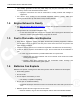
3. Step-By-Step Outline of Installation No. Description 4-2010 No. Description 1 NC 2 Load Control Pin 8 or 9 3 Ground Pin 4 4 From Circuit Breaker 5 To Load Relay Requirements: · Input: 12Vdc, Max 0.5 Amp · Contact: 120 V AC, Amp rating for load · Mounting: Typically in distribution panel FIGURE 10. HIGH VOLTAGE RELAY DPDT 220V AC LOAD 3.6.7 Ethernet Connections Wire The generator set control board has a connector for Cat 5 Ethernet cable for connection to a remote modem/router.
4-2010 3. Step-By-Step Outline of Installation An optional thermostatically controlled battery heater is available for more reliable starting in ambient temperatures down to -20 °F (-28.8 °C). The heater wraps around the battery. The heater cord is connected to the 120V, accessory junction box. Install the heater in accordance with the kit instructions.
3. Step-By-Step Outline of Installation 4-2010 In all fuel system installations, cleanliness is extremely important. · Make every effort to prevent fuel contamination of: · moisture · dirt · excess thread sealant · contaminants of any kind · Clean all fuel system components before installing. Gaseous-fuel supply system design, materials, components, fabrication, assembly, installation, testing, inspection, operation and maintenance must comply with the applicable codes. See NFPA Standards No.
4-2010 3. Step-By-Step Outline of Installation Callout Number Component 12 Fuel Connection (Female) 3/4 NPT & NG & LPV 13 4x Anchoring Spike FIGURE 12. FUEL LINE CONNECTIONS 3.7.2 Fuel Line Connections (Model 14GSBB-6716A Only) An Australian Gas Association (AGA) approved shutoff valve must be installed prior to generator set installation in Australia or New Zealand. Adaptation from NPT to BSPT may be required, depending on the valve used.
3. Step-By-Step Outline of Installation 4-2010 See the Generator Set Specifications Table for fuel specifications, such as BTU. To determine the required meter capacity, generator set consumption must be added to the gas consumed for heating, cooking, clothes drying, etc. · A typical installation might require a 400,000 BTU meter. Consideration should also be given to utilizing high pressure gas supply (2 psi) if available.
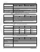
4-2010 3. Step-By-Step Outline of Installation TABLE 20. NATURAL GAS PIPE CAPACITY - CUBIC FEET OF GAS PER HOUR Normal Iron Pipe Size (Inches) Length of Pipe in Feet 10 20 3/4 360 250 1 680 1 1/4 1400 30 40 50 60 70 465 375 320 285 260 240 950 770 660 580 530 490 80 90 100 125 150 175 200 460 430 400 360 325 300 280 Maximum pipe capacity in cubic feet per hour of 0.60 specific gravity Natural Gas with a pressure drop of 0.5 inches (1.27 mm) WC over the length. 3.
3. Step-By-Step Outline of Installation 4-2010 TABLE 21. REQUIRED PROPANE TANK SIZE IN GALLONS (LITERS) FOR INDICATED TEMPERATURES WHEN KEPT AT LEAST HALF FULL Withdrawal Rate Lowest Average Winter Temperature 32 °F (0 °C) 20 °F (-7 °C) 10 °F (-12 °C) 0 °F (-18 °C) -10 °F (-23 °C) -20 °F (-29 °C) -30°F (-34 °C) 100 cfg (250,000 BUT/hr) [2.8 m3/hr (264 MJ/hr)] 250 (945) 250 (945) 250 (945) 400 (1515) 500 (1890) 1000 (3785) 1500 (5675) 150 cfg (375,000 BUT/hr) [4.2 m3/hr(395.
4-2010 3. Step-By-Step Outline of Installation TABLE 22.
3. Step-By-Step Outline of Installation 4-2010 After assembly, and before initial operation, all fuel system connections, hose valves, regulators and fittings must be tested and proven free of leaks using a soap-and-water (or equivalent) solution while the system is under gas or air pressure of at least 1.5 times the supply pressure or 3 psi (20.7 kPa) minimum. · Apply the soap-and-water solution to all fuel system connections, hose valves, regulators and fittings.
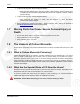
4 Optional Internet/Email Interface Descriptions 4.1 Introduction This feature allows for in-home or remote access to your generator set through a web page. On this web page, you can start or stop the generator set, adjust the exerciser day and time, determine if utility power is available and view the last 20 events/faults on the generator set. This feature is useful for homeowners who travel or have a second home and want to be able to remotely interface with their generator set.
4. Optional Internet/Email Interface Descriptions 4.2 4-2010 Screen Descriptions FIGURE 15. HOME PAGE 4.2.1 Setting Time and Date Select the Genset Time/Date Tab on the Home Screen to set the time and date for the generator set control. FIGURE 16.
4-2010 4.2.2 4. Optional Internet/Email Interface Descriptions Set Exercise Schedule Select the Exercise Schedule Tab on the Home Screen to set the generator set exercise schedule. NOTE: The generator set will exercise on the first scheduled day for which it is programmed. After that it exercises on that day at the scheduled interval. For example, if the generator set is scheduled on a Wednesday for Saturdays with a monthly interval, the generator set starts on the next available Saturday.
4. Optional Internet/Email Interface Descriptions 4-2010 FIGURE 19. EVENT LOG 4.2.5 Fault Log Select the Fault Log Tab on the Home Screen to review the last 5 faults. FIGURE 20. FAULT LOG 4.2.6 Network Setup Screen Descriptions An owner-custom password can be defined in the Network Setup screen shown below. The user will be prompted to enter the User Name and Password to access this screen. The Network Setup Parameters screen allows dynamic addresses to be changed to static addresses.
4-2010 4. Optional Internet/Email Interface Descriptions FIGURE 22. NETWORK SETUP PARAMETERS 4.2.7 Email Setup Screen Descriptions The user must determine what events will trigger an email notification of the event: · Never · All Events · Maintenance and Attention Required or Attention Required Only This screen is also used to set up e-mail configuration. The user may enter up to three email addresses for receiving notifications of the home-standby generator set status.
4. Optional Internet/Email Interface Descriptions 4-2010 FIGURE 25.
5 Ethernet Connection Installation Worksheet: NOTE: IMPORTANT: Leave a filled-out copy of this sheet (chapter) with the customer for future reference. This generator set provides in-home network capability and Internet connectivity. It is the owner's responsibility to provide a network specialist for these connections and setup. The following gives guidance for gathering information and materials needed for a network specialist to enable all features. NOTE: 5.
5. Ethernet Connection Installation Worksheet: 5.3.2 4-2010 Email/Internet Service Provider (ISP) DSL, Cable, Satellite, etc. This will support Email Notification. The service provider must be contacted to verify and provide the following information. NOTE: If these items cannot be verified or provided, email communication and/or remote Internet access may not work.
6 Optional Internet/Email Interface Setup 6.1 Ethernet Connections (Optional) Wiring connections to the Ethernet RJ-45 plug are shown in the Ethernet RJ-45 Connector Wiring illustration. Utilize an appropriate Ethernet stripping and crimping tool for these connections. FIGURE 26. ETHERNET CONNECTOR FIGURE 27.
6. Optional Internet/Email Interface Setup 4-2010 FIGURE 28. NETWORK CONNECTIONS 6.2 In-Home Network Access to the Generator Set 1. Connect an Ethernet cable from the generator set control board to a router that has enough ports to connect the generator set and a computer. 2. Write down the IP Address (shown on the Network Setup screen below) on the generator set's in-home operator panel. NOTE: Leave the DHCP ON. 3.
4-2010 6. Optional Internet/Email Interface Setup Password: Cummins The following screen will be displayed after a few seconds. NOTE: It may take a few seconds for the screen and screen updates to load. FIGURE 29.
6. Optional Internet/Email Interface Setup 4-2010 FIGURE 30. NETWORK SETUP SCREEN ON THE IN-HOME OPERATOR PANEL FIGURE 31. NETWORK SETUP SCREEN FIGURE 32. NETWORK SETUP (PAGE 1) 6.3 Setting up E-mail Notification 1. See In-Home Network Access to the Generator Set to set up the in-home network. 2. Click on the Network Setup Tab.
4-2010 6. Optional Internet/Email Interface Setup 3. Click Click here to start Network Setup. 4. Set up in-home computer access to the generator set. 5. Click Network Setup on the home page. 6. Click Click here to start Network Setup. 7. Continue to the Email Setup screen. 8. Select the Alert Level you would like to receive. 9. Enter your e-mail Server Name, User Name (inclusive of domain - for example. usename@yahoo.com) and Password.
6. Optional Internet/Email Interface Setup 4-2010 FIGURE 34. NETWORK SETUP SCREEN FIGURE 35. NETWORK SETUP PARAMETERS FIGURE 36. EMAIL SETUP PARAMETERS FIGURE 37. EMAIL ADDRESSES FIGURE 38.
4-2010 6.5 6. Optional Internet/Email Interface Setup Remote Internet Access to the Generator Set WARNING: Opening ports in your firewall can pose network security risks. The following instructions require forwarding port 80. NOTE: It is highly recommended that a professional computer and network support specialist be hired to complete this part of the setup for proper connections and proper firewall protection to the in-home network. 1.
6. Optional Internet/Email Interface Setup 4-2010 Answer: Yes, a router or switch is required to allow for the connection of more than one device (computer, generator set, etc.) with each other and the Internet. · Typically, your Internet modem also serves as a router. · If you have an available Ethernet connection on your router-enabled modem, you may not need to add an additional router.
4-2010 6. Optional Internet/Email Interface Setup Answer: Static IP addresses are required if you plan to access your generator set remotely via the Internet. Question: I used the IP Addresses shown on the front of this guide, but why was I not able to access the generator set? Answer: The IP Addresses shown in this guide are only examples and are not likely to be the ones that will work on your network setup.
6. Optional Internet/Email Interface Setup 4-2010 This page is intentionally blank.
7 Operation 7.1 3 Position Switch A three-position Start/Stop switch is located at the genset control panel. Switch positions available: · Manual Start: Normally only the maintenance/service technician has occasion to manually start and stop the generator set. Push the switch down at the thick end to start the set immediately. · Stop (middle position): This switch disables the set.
7. Operation 7.2 4-2010 In-Home Operator Panel The operator panel must be hard-wired to the generator set in order for the generator system to operate. NOTE: The in-home operator panel and Internet/Email interface can be used simultaneously The operator panel consists of two UTILITY status lamps, three GENERATOR status lamps, three action buttons and an LCD display screen with four navigation buttons. No.
4-2010 7.3 7. Operation Typical Operation NOTE: The following diagrams are based on an APPROXIMATE time duration. Your genset may vary slightly from the timing diagrams in this manual. FIGURE 41.
7. Operation 4-2010 FIGURE 42.
4-2010 7. Operation FIGURE 43.
7. Operation 4-2010 FIGURE 44. LOAD MANAGEMENT TIMING DIAGRAM 7.3.1 Normal Operation: Utility Power Available and Connected As long as utility power is available and connected, both of the green UTILITY lamps (PRESENT and CONNECTED) will stay on and the LCD screen will indicate “Genset Stopped". If the red GENERATOR STANDBY OFF light is on, the generator set will not start up automatically if utility power is interrupted.
4-2010 7. Operation FIGURE 45. UTILITY PRESENT AND CONNECTED—STANDBY OFF LAMP ON 7.3.2 Emergency Operation: Utility Power Interrupted If utility power is interrupted, 1. The green UTILITY PRESENT lamp will go out 2. The generator set will start automatically and the green GENERATOR RUNNING lamp will turn on. 3. The UTILITY CONNECTED light will go out when the generator set is connected to supply power. The LCD screen will provide a visual indication of “Genset Load" (bar graphs).
7. Operation 7.4 4-2010 To Enable/Disable Standby Normally, you should not have to disable generator set STANDBY. · STANDBY should always be enabled (ON) except during maintenance/service. · STANDBY will have to be re-enabled (STANDBY OFF light on) if the generator set is started or stopped manually (normally a maintenance/service function) or a fault shutdown has occurred. CAUTION: When STANDBY is disabled the generator set will NOT automatically start to supply power if utility power is interrupted.
4-2010 7. Operation 2. Press START to manually start the generator set and connect it to supply power to the house. The STANDBY OFF lamp will come on and the display will state: “Genset started manually (Standby Ready Disabled)." 3. Press STOP to manually stop the generator set and disconnect it. The STANDBY OFF lamp will come on and the display will state: “Genset stopped manually (Standby Ready Disabled).
7. Operation 4-2010 · Perform the maintenance. Press the BACK button to return to the home screen. FIGURE 50. TYPICAL MAINTENANCE DUE SCREEN 7.6.3 New Event Screen A New Event screen appears whenever system status changes, such as when there is an interruption of utility power. The screen provides a brief description of the event along with the time and date of the event. · The message does not time out, unless superseded by a new event. · Press the BACK button to return to the home screen.
4-2010 7. Operation FIGURE 52. GENERATOR SET STATUS SCREEN 7.8 Display Setup and Software Info 7.8.1 Brightness and Contrast To change the Brightness and Contrast of the display screen: 1. Press the MENU button on the home screen. 2. Press the up or down arrow button on the menu screen to select Display Setup. 3. Press the ENTER button on the menu screen. 4. Press the NEXT button to select Brightness or Contrast. 5. Press the increase or decrease arrow button to increase or decrease brightness. 6.
7. Operation 4-2010 FIGURE 53. DISPLAY SETUP AND SOFTWARE INFO SCREENS 7.8.2 Software Info To check on the generator set and display software: 1. Press the MENU button on the home screen. 2. Press the up or down arrow button on the menu screen to select Display Setup. 3. Press the ENTER button on the menu screen. 4. Press the INFO button on the Display Setup screen and note the values displayed on the Software Info screen.
4-2010 7. Operation 5. Press the BACK button to return to the home screen. 7.9 Event Log 7.9.1 To Check Log of Last 20 Events 1. Press the MENU button on the home screen. 2. Press the up or down arrow button on the menu screen to select Event Log. 3. Press the ENTER button on the menu screen. 4. Scroll through the event log with the up and down double-arrow buttons. Each screen provides a brief description of the event along with the time and date of the event. 5.
7.
4-2010 7. Operation FIGURE 55. FAULT LOG SCREEN 7.11 Exercise Settings To set the generator set exercise schedule: 1. Press the EXCER button on the home screen. 2. Press the NEXT button on the Exerciser Clock screen to select the field to change. 3. Press the up or down arrow button to increase or decrease the frequency of exercise and the day of the week and time of day for exercise.
7. Operation 4-2010 Weekly Bimonthly Monthly Never 4. Press the BACK button to save the settings and return to the home screen. 5. If you want to exercise the generator set now, select Exercise Now, and press either the up or down arrow. NOTE: Scheduled or prompted exercise does not transfer the house loads to the generator set. FIGURE 56. EXERCISE CLOCK SCREEN 7.12 Time Setup To set up the generator set clock for the current date and time: 1. Press the CLOCK button on the home screen. 2.
4-2010 7. Operation FIGURE 57. TIME SETUP SCREEN 7.13 Load Management The generator set may have been set up at installation to connect and disconnect certain large loads, such as air conditioners, to manage the total load so as not to overload the generator set. This requires the installation of relays to the load management signals which allow for the disconnection of loads. Load management can be set to operate in automatic or manual mode.
7. Operation 4-2010 7.13.2 Manual Load Management CAUTION: To reduce unnecessary loss of service, it is highly recommended that manual load management be undertaken only by an authorized Cummins Onan dealer. When set to manual mode, the user is able to view, connect, and disconnect loads. If the connection of loads L1 and L2 exceeds generator capacity, the AC circuit breaker trips. To select manual load management when the generator is running: 1. Press the LOAD button on the home screen. 2.
8 Startup and Configuration 8.1 Installation Review Before starting the genset inspect the installation and check off each of the following questions if it can be answered “YES". If a question cannot be checked off, review the appropriate section in the manual.
8. Startup and Configuration 4-2010 If the situation occurs, close the main valve at the tank and vent the fuel from the line at the tank. After reconnecting the lines, start the crank cycle at the genset and then turn on the fuel at the tank while the engine is cranking. Multiple crank attempts may be required to purge the fuel line depending on the length of the run. 8.
4-2010 8. Startup and Configuration FIGURE 59. GENERATOR CONFIGURATION 8.5 Transfer Switch Configuration To configure the generator set for the transfer switch being used: 1. Press the MENU button on the home screen.
8. Startup and Configuration 4-2010 2. Press and hold the blank button on the menu screen for at least 5 seconds to go to the Config Menu. 3. Press the up or down arrow button on the Config Menu screen to select TS Config. 4. Press Enter on the Config Menu to go to the Transfer Switch screen. 5. Press the up or down arrow button to select between two choices: “RSS100-6868 and RSS200-6869" or “RSS100-6634 and RSS200-6635," which must match the model number of the transfer switch being used.
4-2010 8. Startup and Configuration FIGURE 60. TRANSFER SWITCH CONFIGURATION 8.6 Transfer Switch Parameter Adjustments Model RSS100-6634 and RSS200-6635 Transfer Switches: Refer to Transfer Switch Installation Manual 962-0620 to set the parameters inside the transfer switch.
8. Startup and Configuration 4-2010 Model RSS100-6868 and RSS200-6869 Transfer Switches: To make transfer switch parameter adjustments: 1. Press the MENU button on the home screen. 2. Press and hold the blank button on the menu screen for at least 5 seconds to go to the Config Menu. 3. Press the up or down arrow button on the Config Menu screen to select TS Adjustments. 4. Press Enter on the Config Menu to go to the Transfer Switch screen. 5.
4-2010 8. Startup and Configuration FIGURE 61. TRANSFER SWITCH ADJUSTMENTS 8.7 Generator Adjustments 8.7.1 To Adjust the Output Voltage Use the following procedure: 1. Connect an accurate AC volt meter across L1 and L2 while the generator set is running.
8. Startup and Configuration 4-2010 2. With Output Volts selected on the Adjustments Menu screen, press the up or down arrow button to adjust the voltage to the desired setting 3. The control allows an adjustment of 240 VAC ± 7% (17 VAC). 4. Press the BACK button to save the settings and return to the home screen. 8.7.2 To Calibrate the Display Meter Use the following procedure: 1. Connect an accurate AC volt meter across L1 and L2 while the generator set is running. 2.
9 Communication Troubleshooting 9.1 In-Home Network Access to Generator Set Troubleshooting WARNING: Some Generator Set service procedures present hazards that can result in severe personal injury or death. Only trained and experienced service personnel with knowledge of fuels, electricity, and machinery hazards should perform Generator Set service. Possible Causes: Bad connections or bad communications Corrective Actions: 1. Check connections. a.
9. Communication Troubleshooting 4-2010 FIGURE 63. NETWORK CONNECTIONS (CONTROL BOARD AND ETHERNET CONNECTION) 9.2 Remote Internet Access to Generator Set Troubleshooting WARNING: Some Generator Set service procedures present hazards that can result in severe personal injury or death. Only trained and experienced service personnel with knowledge of fuels, electricity, and machinery hazards should perform Generator Set service.
4-2010 9. Communication Troubleshooting 7. Check to see if you can access a standard web page from a computer. · If not, contact the ISP to troubleshoot the internet connection. 8. Verify all settings, as described in the Network Setup Guide. 9. If the previous steps do not correct the problem, contact a computer network specialist to diagnose. * To verify your IP Address, access “whatismyipaddress.com" from the browser of a computer connected to the internet and on the same network as the generator set.
9. Communication Troubleshooting 4-2010 8. Verify with your ISP that the Static DNS (Domain Name Server) #1 and #2 are correct. 9. If the previous steps do not correct the problem, contact a computer network specialist to diagnose. ** “No authentication" is possible by leaving the username and password fields blank. IMPORTANT NOTE: Changes are not saved unless you navigate through all three Network Setup screens and click on “Done". The message “Settings Saved Successfully" is then displayed. FIGURE 64.
4-2010 9. Communication Troubleshooting FIGURE 65. GENERATOR SET HOME PAGE FIGURE 66.
9. Communication Troubleshooting 4-2010 FIGURE 67.
Appendix A. Outline and System Drawings Table of Contents Figure 68. Wiring Diagram (Sheet 1 of 3) ................................................................................................... 85 Figure 69. Wiring Diagram (Sheet 2 of 3) ................................................................................................... 86 Figure 70. Wiring Diagram (Sheet 3 of 3) ................................................................................................... 87 Figure 71.
Appendix A. Outline and System Drawings 4-2010 This page is intentionally blank.
4-2010 Appendix A. Outline and System Drawings FIGURE 68.
Appendix A. Outline and System Drawings 4-2010 FIGURE 69.
4-2010 Appendix A. Outline and System Drawings FIGURE 70.
Appendix A. Outline and System Drawings 4-2010 FIGURE 71.
4-2010 Appendix A. Outline and System Drawings FIGURE 72.
Appendix A. Outline and System Drawings 4-2010 FIGURE 73.
4-2010 Appendix A. Outline and System Drawings FIGURE 74.
Appendix A. Outline and System Drawings 4-2010 FIGURE 75.
4-2010 Appendix A. Outline and System Drawings FIGURE 76.
Appendix A. Outline and System Drawings 4-2010 This page is intentionally blank.
Cummins Power Generation 1400 73rd Ave. NE Minneapolis, MN 55432 USA Phone 1 763 574 5000 Toll-free 1 800 888 6626 Fax 1 763 574 5298 Copyright © 2010 Cummins Power Generation, Inc. All rights reserved. Cummins, Onan, the "C" logo, and "Performance you rely on." are trademarks of Cummins Inc.