
Installation manual

4-2010 3. Step-By-Step Outline of Installation
3. Mount the operator panel with four No. 6 wood screws or wall anchors.
· On brick, stone or block walls:
1. Mount with spacers to clear the harness connector on the back of the operator panel.
2. Mount with the appropriate wall anchors.
3. Connect the operator panel to the generator set.
Refer to the Outline and System Drawings Appendix of this manual for guidelines on how to
connect the operator panel to the generator set.
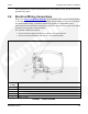
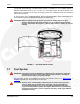
3.6.5.3 Operator Panel Installation In The Generator Set
The operator panel may be installed inside of the generator set.
To install the operator panel in the generator set:
1. Remove the bushing in the 1" hole on the control panel.
2. Remove the 4 small screws from the control panel.
3. Pulling the harness through the 1" hole, connect J4 directly to the back of the operator
panel into the connector that lines up with the hole in the metal panel.
4. Replace the 4 small screws.
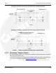
3.6.6 Load Shed Communications Wires
The control cable has the load control wires brought out of the genset (P7-7 and P7-8). Class 1
wiring methods should be used for the in-home display, Ethernet and transfer switch
communication conductors between the generator set and transfer switch. Separation of Class 2
and power circuits should be maintained per Article 725.136 of 2008 NFPA 70: National
Electrical Code.
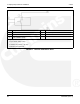
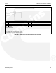
Use 300V 18 gauge 75 °C wire for wiring the relay.
See the following figures for the different ways the relays can be wired.
A029V088 (Issue 2) 21