
Installation manual

3. Step-By-Step Outline of Installation 4-2010
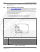
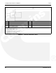
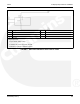
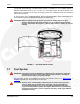
No. Description No. Description
1 NC 2 Load Control Pin 8 or 9
3 Ground Pin 4 4 From Circuit Breaker
5 To Load
Relay Requirements:
· Input: 12Vdc, Max 0.5 Amp
· Contact: 120 V AC, Amp rating for load
· Mounting: Typically in distribution panel
FIGURE 10. HIGH VOLTAGE RELAY DPDT 220V AC LOAD
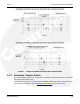
3.6.7 Ethernet Connections Wire
The generator set control board has a connector for Cat 5 Ethernet cable for connection to a
remote modem/router. See Ethernet/Email Interfacefor setup and operation.
Use Cat 5 Ethernet cable and 300V 18 gauge 75 °C wire for wiring the relay.
Class 1 wiring methods should be used for the in-home display, Ethernet and transfer switch
communication conductors between the generator set and transfer switch. Separation of Class 2
and power circuits should be maintained per Article 725.136 of 2008 NFPA 70: National
Electrical Code.
NOTE: The Internet/Email interface requires “high speed" or “broadband" cable or
DSL service to the house. See Ethernet/Email Interface for a full list of
requirements.
3.6.8 Battery
The generator set has a 12 VDC, negative-ground control and engine cranking system. The
engine has a battery charger for recharging during generator set operation.
A battery charger located in the transfer switch keeps the battery charged during generator set
standby.
Refer to the GSBB Specifications Table for battery specifications.
24 A029V088 (Issue 2)