
Specifications
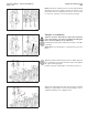
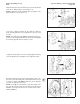
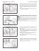
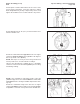
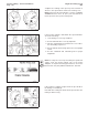
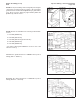

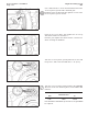
Table Of Contents
- COVER PAGE
- FOREWORD
- TABLE OF CONTENTS
- INTRODUCTION
- GROUP 0 - ENGINE DISASSEMBLY AND ASSEMBLY
- COOLANT - DRAINAGE
- ENGINE DISASSEMBLY AND ASSEMBLY - SERVICE TOOLS
- ENGINE DISASSEMBLY AND ASSEMBLY - GENERAL INFORMATION
- ENGINE - PREPARATION FOR CLEANING
- COOLANT FILTER - REMOVAL
- LUBRICATING OIL FILTER - REMOVAL
- CRANKCASE BREATHER - REMOVAL
- TURBOCHARGER - REMOVAL
- EXHAUST MANIFOLD - REMOVAL
- STARTING MOTOR - REMOVAL
- FAN AND FAN SPACER - REMOVAL
- ALTERNATOR BELTS - REMOVAL
- ALTERNATOR - REMOVAL
- ALTERNATOR MOUNTING BRACKET - REMOVAL
- LUBRICATING OIL COOLER ASSEMBLY - REMOVAL
- COOLANT INLET TRANSFER CONNECTION - REMOVAL
- DIPSTICK TUBE AND HOUSING - REMOVAL
- PISTON COOLING NOZZLES - REMOVAL
- WATER HEADER COVERS - REMOVAL
- ENGINE - INSTALLATION ON THE REBUILD STAND
- FLYWHEEL - REMOVAL
- FLYWHEEL HOUSING - REMOVAL
- REAR COVER - REMOVAL
- CRANKSHAFT SEAL, REAR - REMOVAL
- FAN BELTS - REMOVAL
- FAN HUB AND FAN HUB SUPPORT BRACKET - REMOVAL
- WATER PUMP BELT - REMOVAL
- CELECT™ COOLANT TEMPERATURE SENSOR - REMOVAL
- THERMOSTAT HOUSING - REMOVAL
- AIR COMPRESSOR COOLANT INLET AND OUTLET TUBES - REMOVAL
- WATER PUMP - REMOVAL
- ACCESSORY DRIVE PULLEY - REMOVAL
- VIBRATION DAMPER - REMOVAL
- ENGINE SUPPORT BRACKET, FRONT - REMOVAL
- STC EXTERNAL OIL PLUMBING - REMOVAL
- STC OIL CONTROL VALVE - REMOVAL
- CELECT™ ACTUATOR HARNESS - REMOVAL
- CELECT™ SENSOR HARNESS - REMOVAL
- CELECT™ ELECTRONIC CONTROL MODULE (ECM) - REMOVAL
- CELECT™ AMBIENT AIR PRESSURE SENSOR -REMOVAL
- CELECT™ LUBRICATING OIL PRESSURE SENSOR - REMOVAL
- CELECT™ ECM COOLING PLATE - REMOVAL
- FUEL PUMP - REMOVAL
- AIR COMPRESSOR - REMOVAL
- ACCESSORY DRIVE - REMOVAL
- FUEL TUBING - REMOVAL
- CELECT™ ENGINE POSITION SENSOR (EPS) - REMOVAL
- LUBRICATING OIL TRANFER TUBE - REMOVAL
- LUBRICATING OIL PUMP SIGNAL LINE - REMOVAL
- LUBRICATING OIL PUMP - REMOVAL
- VISCOSITY SENSOR - REMOVAL
- CELECT™ BOOST PRESSURE SENSOR - REMOVAL
- CELECT™ INTAKE AIR TEMPERATURE SENSOR - REMOVAL
- INTAKE MANIFOLD - REMOVAL
- ROCKER HOUSING COVERS - REMOVAL
- ENGINE BRAKES - REMOVAL
- ROCKER LEVER SHAFT ASSEMBLIES - REMOVAL
- VALVE CROSSHEADS - REMOVAL
- PUSH TUBES - REMOVAL
- INJECTORS - REMOVAL
- ROCKER LEVER HOUSING - REMOVAL
- FUEL CROSSOVERS - REMOVAL
- CYLINDER HEADS - REMOVAL
- CAM FOLLOWER ASSEMBLIES - REMOVAL
- CAMSHAFT BEARING SUPPORT - REMOVAL
- LUBRICATING OIL PAN - REMOVAL
- GEAR COVER - REMOVAL
- CRANKSHAFT SEAL, FRONT - REMOVAL
- ACCESSORY DRIVE SEAL - REMOVAL
- CAMSHAFT - REMOVAL
- PISTON AND CONNECTING ROD ASSEMBLIES - REMOVAL
- CYLINDER LINERS - REMOVAL
- CRANKSHAFT - REMOVAL
- CYLINDER BLOCK - REMOVAL FROM THE REBUILD STAND
- CYLINDER BLOCK - INSTALLATION ON THE REBUILD STAND
- CRANKSHAFT - INSTALLATION
- CYLINDERS LINERS - INSTALLATION
- PISTON AND CONNECTING ROD ASSEMBLIES - ASSEMBLY AND INSTALLATION
- REAR COVER - INSTALLATION
- CRANKSHAFT SEAL, REAR - INSTALLATION
- FLYWHEEL HOUSING - INSTALLATION
- FLYWHEEL - INSTALLATION
- CYLINDER HEADS - INSTALLATION
- CAMSHAFT INSTALLATION
- CAM FOLLOWER ASSEMBLIES - INSTALLATION
- INJECTION TIMING - GENERAL INFORMATION
- ACCESSORY DRIVE - INSTALLATION
- CELECT™ ENGINE POSITION SENSOR (EPS) - INSTALLATION
- LUBRICATING OIL PUMP - INSTALLATION
- GEAR COVER - INSTALLATION
- CRANKSHAFT SEAL, FRONT - INSTALLATION
- CAMSHAFT BEARING SUPPORT - INSTALLATION
- ACCESSORY DRIVE SEAL - INSTALLATION
- ACCESSORY DRIVE PULLEY - INSTALLATION
- LUBRICATING OIL PAN - INSTALLATION
- FUEL CROSSOVERS - INSTALLATION
- ROCKER LEVER HOUSING - INSTALLATION
- INJECTORS - INSTALLATION
- PUSH TUBES - INSTALLATION
- VALVE CROSSHEADS - INSTALLATION
- ROCKER LEVER SHAFT ASSEMBLIES - INSTALLATION
- INJECTOR AND VALVE ADJUSTMENT
- ENGINE BRAKE - INSTALLATION
- ENGINE BRAKE ADJUSTMENT
- ROCKER HOUSING COVERS - INSTALLATION
- INTAKE MANIFOLD - INSTALLATION
- CELECT™ INTAKE AIR TEMPERATURE SENSOR - INSTALLATION
- CELECT™ BOOST PRESSURE SENSOR - INSTALLATION
- VISCOSITY SENSOR - INSTALLATION
- LUBRICATING OIL PUMP SIGNAL - INSTALLATION
- LUBRICATING OIL TRANSFER TUBE - INSTALLATION
- FUEL TUBING - INSTALLATION
- AIR COMPRESSOR - INSTALLATION
- FUEL PUMP - INSTALLATION
- CELECT™ ECM COOLING PLATE - INSTALLATION
- CELECT™ LUBRICATING OIL PRESSURE SENSOR - INSTALLATION
- CELECT™ AMBIENT AIR PRESSURE SENSOR - INSTALLATION
- CELECT™ ELECTRONIC CONTROL MODULE (ecm) - INSTALLATION
- CELECT™ SENSOR HARNESS - INSTALLATION
- CELECT™ ACTUATOR HARNESS - INSTALLATION
- STC OIL CONTROL VALVE - INSTALLATION
- STC EXTERNAL OIL PLUMBING - INSTALLATIONing - Installa-tion
- ENGINE SUPPORT BRACKET, FRONT - INSTALLATION
- VIBRATION DAMPER - INSTALLATION
- WATER PUMP - INSTALLATION
- WATER PUMP BELT - INSTALLATION AND ADJUSTMENT
- THERMOSTAT HOUSING - INSTALLATION
- CELECT™ COOLANT TEMPERATURE SENSOR - INSTALLATION
- AIR COMPRESSOR COOLANT INLET AND OUTLET TUBES - INSTALLATION
- FAN HUB AND FAN HUB SUPPORT - INSTALLATION
- FAN BELTS - INSTALLATION AND ADJUSTMENT
- ENGINE - REMOVAL FROM THE REBUILD STAND
- PISTON COOLING NOZZLES - INSTALLATION
- DIPSTICK TUBE AND HOUSING - INSTALLATION
- WATER HEADER COVERS - INSTALLATION
- COOLANT INLET TRANSFER CONNECTION - INSTALLATION
- LUBRICATING OIL COOLER ASSEMBLY - INSTALLATION
- ALTERNATOR MOUNTING BRACKET - INSTALLATION
- ALTERNATOR - INSTALLATION
- ALTERNATOR BELTS - INSTALLATION AND ADJUSTMENT
- FAN AND FAN SPACER - INSTALLATION
- STARTING MOTOR - INSTALLATION
- EXHAUST MANIFOLD - INSTALLATION
- TURBOCHARGER - INSTALLATION
- CRANKCASE BREATHER TUBE - INSTALLATION
- LUBRICATING OIL FILTER - INSTALLATION
- COOLANT FILTER - INSTALLATION
- ENGINE - COVERING ALL OPENINGS
- GROUP 1 - CYLINDER BLOCK
- CYLINDER BLOCK - SERVICE TOOLS
- CYLINDER BLOCK - EXPLODED VIEW
- CYLINDER BLOCK - GENERAL INFORMATION
- CYLINDER BLOCK - DISASSEMBLY
- CYLINDER BLOCK - CEANING AND INPECTION
- CYLINDER BLOCK - MACHINING
- CYLINDER BLOCK COUNTERBORE - INSPECTION AND MACHINING
- CYLINDER BLOCK - ASSEMBLY
- CYLINDER LINERS - CLEANING AND INSPECTION
- PISTONS - CLEANING AND INSPECTION
- CONNECTING ROD ASSEMBLIES - CLEANING AND INSPECTION
- CONNECTING RODS - BEND AND TWIST INSPECTION
- CONNECTING ROD BEARINGS - CLEANING AND INSPECTION
- CRANKSHAFT ADAPTER - CLEANING AND INSPECTION
- CRANKSHAFT PULLEY - CLEANING AND INSPECTION
- VIBRATION DAMPER - CLEANING AND INSPECTION
- CRANKSHAFT - CLEANING AND INSPECTION
- CRANKSHAFT GEAR - REPLACEMENT
- CRANKSHAFT BEARINGS - CLEANING AND INSPECTION
- CAMSHAFT - CLEANING AND INSPECTION
- CAMSHAFT GEAR - REPLACEMENT
- GEAR COVER - CLEANING AND INSPECTION
- REAR COVER - CLEANING AND INSPECTION
- MAGNETIC CRACK INSPECTION
- GROUP 2 - CYLINDER HEAD
- CYLINDER HEAD - SERVICE TOOLS
- CYLINDER HEA D - EXPLODED VIEW
- CYLINDER HEAD - GENERAL INFORMATION
- CYLINDER HEAD - CLEANING AND INSPECTION FOR REUSE
- CYLINDER HEAD - REBUILD
- CYLINDER HEAD - REPLACING THE VALVE GUIDES
- CYLINDER HEAD - RING DOWEL REPLACEMENT
- CYLINDER HEAD - REPLACING THE VALVE SEAT INSERTS
- CYLINDER HEAD - GRINDING THE VALVES
- CYLINDER HEAD - REPLACING THE INJECTOR SLEEVES
- CYLINDER HEAD - PRESSURE TESTING
- CYLINDER HEAD - MAGNETIC PARTICLE CHECKING
- CYLINDER HEAD - VACUUM TESTING VALVE SEATING FOR REUSE
- CYLINDER HEAD - VALVES - MAGNETIC CRACK INSPECTION
- VALVE CROSSHEAD - CLEANING AND CHECKING FOR REUSE
- VALVE CROSSHEAD - MAGNETIC CRACK INSPECTION
- GROUP 3 - ROCKER LEVER HOUSING ASSEMBLY
- ROCKER LEVER HOUSING ASSEMBLY - SERVICE TOOLS
- ROCKER LEVER HOUSING COVER - EXPLODED VIEW
- ROCKER LEVER HOUSING ASSEMBLY - EXPLODED VIEW
- WATER MANIFOLD PLUMBING - EXPLODED VIEW
- ROCKER LEVER HOUSING ASSEMBLY - GENERAL INFORMATION
- ROCKER LEVER - CLEANING AND INSPECTION FOR REUSE
- ROCKER LEVER BUSHING - REPLACEMENT
- ROCKER LEVER - MAGNETIC CRACK INSPECTION
- ROCKER HOUSING COVERS - CLEANING AND INSPECTION FOR REUSE
- ROCKER LEVER HOUSING ASSEMBLY - CLEANING AND INSPECTION FOR REUSE
- STC OIL PLUMBING - CLEANING AND INSPECTION FOR REUSE
- RING AND PIN DOWEL - REPLACEMENT
- METRI-PACK PASS THROUGH CONNECTOR - REPLACEMENT
- GROUP 4 - CAM FOLLOWER ASSEMBLY
- CAM FOLLOWER ASSEMBLY - SERVICE TOOLS
- CAM FOLLOWER ASSEMBLY - EXPLODED VIEW
- CAM FOLLOWER ASSEMBLY - GENERAL INFORMATION
- CAM FOLLOWER ASSEMBLY - CLEANING AND INSPECTION FOR REUSE
- CAM FOLLOWER ASSEMBLY - REBUILD
- CAM FOLLOWER LEVER - ROLLER REPLACEMENT
- CAM FOLLOWER SOCKET - REPLACEMENT
- PUSH ROD - CLEANING AND INSPECTION FOR REUSE
- GROUP 5 - FUEL SYSTEM
- GROUP 6 - INJECTORS AND FUEL LINES
- INJECTOR - PT (TYPE D) STEP TIMING CONTROL - EXPLODED VIEW
- INJECTOR - CELECT - EXPLODED VIEW
- INJECTORS - PT (TYPE D) STEP TIMING CONTROL (STC) GENERAL INFORMATION
- INJECTORS - CELECT - GENERAL INFORMATION
- STEP TIMING CONTROL (STC) OIL CONTROL VALVE - GENERAL INFORMATION
- INJECTORS - CLEANING THE EXTERIOR AND INSPECTION FOR REUSE
- INJECTORS - REBUILD
- INJECTORS - CALIBRATION
- STC OIL CONTROL VALVE - CLEANING
- FUEL TUBES, FITTINGS, AND MOUNTING PARTS - CLEANING AND INSPECTION FOR REUSE
- GROUP 7 - LUBRICATING OIL SYSTEM
- LUBRICATING OIL SYSTEM - SERVICE TOOLS
- LUBRICATING OIL SYSTEM - EXPLODED VIEW
- LUBRICATING OIL PUMP ASSEMBLY - EXPLODED VIEW
- LUBRICATING OIL COOLER - EXPLODED VIEW
- LUBRICATING OIL SYSTEM - GENERAL INFORMATION
- LUBRICATING OIL PAN - CLEANING AND INSPECTION FOR REUSE
- LUBRICATING OIL TRANSFER TUBE - CLEANING AND INSPECTION FOR REUSE
- LUBRICATING OIL DIPSTICK AND DIPSTICK TUBE - CLEANING AND INSPECTION FOR REUSE
- LUBRICATING OIL DIPSTICK - CALIBRATION
- LUBRICATING OIL PUMP - CLEANING AND INSPECTION FOR REUSE
- LUBRICATING OIL PUMP - REBUILD
- LUBRICATING OIL PUMP BODY AND COVER BUSHING - REPLACEMENT
- LUBRICATING OIL PUMP DRIVEN GEAR BUSHING - REPLACEMENT
- LUBRICATING OIL PUMP DRIVE GEAR OR SHAFT - REPLACEMENT
- LUBRICATING OIL PUMP DRIVEN SHAFT - REPLACEMENT
- LUBRICATING OIL COOLER ASSEMBLY REBUILD
- GROUP 8 - COOLING SYSTEM
- COOLING SYSTEM - SERVICE TOOLS
- N14 WATER PUMP AND IDLER ASSEMBLY - EXPLODED VIEW
- WATER PUMP AND IDLER ASSEMBLY - GENERAL INFORMATION
- WATER PUMP ASSEMBLY
- WATER PUMP ASSEMBLY - REBUILD
- WATER PUMP IDLER ASSEMBLY - CLEANING AND INSPECTION
- WATER PUMP IDLER ASSEMBLY - REBUILD
- THERMOSTAT HOUSING - CLEANING AND INSPECTION
- COOLANT FILTER HEAD INSERT
- COOLANT FILTER SHUTOFF VALVE
- FAN - CLEANING AND INSPECTION
- WATER TRANSFER TUBES - CLEANING AND INSPECTION
- GROUP 9 - DRIVE UNITS
- DRIVE UNITS - SERVICE TOOLS
- ACCESSORY DRIVE - EXPLODED VIEW
- DRIVE UNITS - GENERAL INFORMATION
- ACCESSORY DRIVE - CLEANING AND INSPECTION FOR REUSE
- ACCESSORY DRIVE - REBUILD
- ACCESSORY DRIVE GEAR - REPLACEMENT
- ACCESSORY DRIVE PULLEY - CLEANING AND INSPECTION FOR REUSE
- ACCESSORY DRIVE PULLEY WEAR SLEEVE - REPLACEMENT
- GROUP 10 - INTAKE AIR SYSTEM
- GROUP 11 - EXHAUST SYSTEM
- GROUP 12 - AIR EQUIPMENT
- GROUP 13 - ELECTRICAL EQUIPMENT
- GROUP 14 - ENGINE TESTING
- GENERAL INFORMATION
- DEFINITION OF TERMS ON ENGINE PERFORMANCE CURVE
- GENERAL RUN-IN PROCEDURES
- GENERAL ENGINE TEST/RUN-IN SPECIFICATIONS
- ENGINE TESTING - SERVICE TOOLS
- ENGINE DYNAMOMETER - INSTALL ENGINE
- PRIMING THE LUBRICATING OIL AND FUEL SYSTEMS
- ENGINE RUN-IN PROCEDURE - ENGINE DYNAMOMETER
- CHASSIS DYNAMOMETER OPERATION
- GENERAL TEST PROCEDURE - CHASSIS DYNAMOMETER
- ENGINE RUN-IN PROCEDURE - CHASSIS DYNAMOMETER
- ENGINE RUN-IN PROCEDURE WITHOUT DYNAMOMETER
- ENGINE PAINTING
- ENGINE STORAGE - SHORT TERM
- ENGINE STORAGE - LONG TERM
- GROUP 15 - INSTRUMENTS AND CONTROLS
- GROUP 16 - MOUNTING ADAPTATIONS
- GROUP 18 - SPECIFICATIONS
- GENERAL ENGINE SPECIFICATIONS
- CAPSCREW MARKINGS AND TORQUE VALUES
- PIPE PLUG TORQUE VALUES
- DECIMAL AND METRIC EQUIVALENTS
- SPECIFICATIONS - GENERAL INFORMATION
- ENGINE ASSEMBLY
- CYLINDER BLOCK
- CYLINDER HEAD
- ROCKER LEVER HOUSING ASEMBLY
- CAM FOLLOWER ASSEMBLY
- FUEL PUMP - REBUILD SPECIFICATIONS
- INJECTORS - REBUILD SPECIFICATIONS
- LUBRICATING OIL SYSTEM
- LUBRICATING OIL PUMP - INSPECTION SPECIFICATIONS
- WATER PUMP ASSEMBLY - REBUILD SPECIFICATIONS
- FAN HUB - INSPECTION SPECIFICATIONS
- THERMOSTAT HOUSING ASSEMBLY - REBUILD SPECIFICATIONS
- THERMOSTAT (RESERVE FLOW COOLING) - OPERATING TEMPERATURE
- COOLING SYSTEM - TORQUE VALUES
- FUEL PUMP AND COMPRESSOR DRIVE
- TURBOCHARGER - INSPECTION SPECIFICATIONS
- AIR COMPRESSOR - INSPECTION SPECIFICATIONS
- ENGINE TESTING - TEST SPECIFICATIONS
- VEHICLE BRAKING - REBUILD SPECIFICATIONS
- GROUP 20 - VEHICLE BRAKING
- COMPONENTS MANUFACTURERS: NAMES AND ADDRESSES
- SERVICE LITERATURE
- INDEX
- LITERATURE SURVEY FORM

Align the plunger rod (1) and the injector push rod (3) with
each other, and parallel to the plunger rod.
NOTE: Tighten the clamp handle (2) after the plunger rod is
aligned with the injector push rod.
Loosen the support bracket (4) and slide the bracket
down until the plunger rod (1) engages the injector push
rod (3).
NOTE: The support bracket must be aligned with the ver-
tical line on the clamp handle bracket. The push rod (3) must
be vertically aligned with the plunger rod (1).
Compress the plunger rod tension spring approximately
12.7 mm [0.50-inch], and tighten the support bracket.
Determine the piston top dead center (TDC) on the com-
pression stroke by rotating the crankshaft in the direction
of engine rotation (clockwise) until the piston plunger
reaches its uppermost position.
NOTE: Use only the crankshaft to rotate the engine. The
use of the gears will result in false measurements. Gear lash
must be closed up in the direction of normal rotation (crank-
shaft clockwise ).
Engine Assembly (00-02) Injection Timing - General Information
N14 Page 0-83