
Specifications
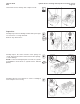


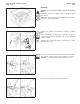
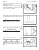
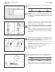
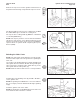
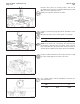
Table Of Contents
- COVER PAGE
- FOREWORD
- TABLE OF CONTENTS
- INTRODUCTION
- GROUP 0 - ENGINE DISASSEMBLY AND ASSEMBLY
- COOLANT - DRAINAGE
- ENGINE DISASSEMBLY AND ASSEMBLY - SERVICE TOOLS
- ENGINE DISASSEMBLY AND ASSEMBLY - GENERAL INFORMATION
- ENGINE - PREPARATION FOR CLEANING
- COOLANT FILTER - REMOVAL
- LUBRICATING OIL FILTER - REMOVAL
- CRANKCASE BREATHER - REMOVAL
- TURBOCHARGER - REMOVAL
- EXHAUST MANIFOLD - REMOVAL
- STARTING MOTOR - REMOVAL
- FAN AND FAN SPACER - REMOVAL
- ALTERNATOR BELTS - REMOVAL
- ALTERNATOR - REMOVAL
- ALTERNATOR MOUNTING BRACKET - REMOVAL
- LUBRICATING OIL COOLER ASSEMBLY - REMOVAL
- COOLANT INLET TRANSFER CONNECTION - REMOVAL
- DIPSTICK TUBE AND HOUSING - REMOVAL
- PISTON COOLING NOZZLES - REMOVAL
- WATER HEADER COVERS - REMOVAL
- ENGINE - INSTALLATION ON THE REBUILD STAND
- FLYWHEEL - REMOVAL
- FLYWHEEL HOUSING - REMOVAL
- REAR COVER - REMOVAL
- CRANKSHAFT SEAL, REAR - REMOVAL
- FAN BELTS - REMOVAL
- FAN HUB AND FAN HUB SUPPORT BRACKET - REMOVAL
- WATER PUMP BELT - REMOVAL
- CELECT™ COOLANT TEMPERATURE SENSOR - REMOVAL
- THERMOSTAT HOUSING - REMOVAL
- AIR COMPRESSOR COOLANT INLET AND OUTLET TUBES - REMOVAL
- WATER PUMP - REMOVAL
- ACCESSORY DRIVE PULLEY - REMOVAL
- VIBRATION DAMPER - REMOVAL
- ENGINE SUPPORT BRACKET, FRONT - REMOVAL
- STC EXTERNAL OIL PLUMBING - REMOVAL
- STC OIL CONTROL VALVE - REMOVAL
- CELECT™ ACTUATOR HARNESS - REMOVAL
- CELECT™ SENSOR HARNESS - REMOVAL
- CELECT™ ELECTRONIC CONTROL MODULE (ECM) - REMOVAL
- CELECT™ AMBIENT AIR PRESSURE SENSOR -REMOVAL
- CELECT™ LUBRICATING OIL PRESSURE SENSOR - REMOVAL
- CELECT™ ECM COOLING PLATE - REMOVAL
- FUEL PUMP - REMOVAL
- AIR COMPRESSOR - REMOVAL
- ACCESSORY DRIVE - REMOVAL
- FUEL TUBING - REMOVAL
- CELECT™ ENGINE POSITION SENSOR (EPS) - REMOVAL
- LUBRICATING OIL TRANFER TUBE - REMOVAL
- LUBRICATING OIL PUMP SIGNAL LINE - REMOVAL
- LUBRICATING OIL PUMP - REMOVAL
- VISCOSITY SENSOR - REMOVAL
- CELECT™ BOOST PRESSURE SENSOR - REMOVAL
- CELECT™ INTAKE AIR TEMPERATURE SENSOR - REMOVAL
- INTAKE MANIFOLD - REMOVAL
- ROCKER HOUSING COVERS - REMOVAL
- ENGINE BRAKES - REMOVAL
- ROCKER LEVER SHAFT ASSEMBLIES - REMOVAL
- VALVE CROSSHEADS - REMOVAL
- PUSH TUBES - REMOVAL
- INJECTORS - REMOVAL
- ROCKER LEVER HOUSING - REMOVAL
- FUEL CROSSOVERS - REMOVAL
- CYLINDER HEADS - REMOVAL
- CAM FOLLOWER ASSEMBLIES - REMOVAL
- CAMSHAFT BEARING SUPPORT - REMOVAL
- LUBRICATING OIL PAN - REMOVAL
- GEAR COVER - REMOVAL
- CRANKSHAFT SEAL, FRONT - REMOVAL
- ACCESSORY DRIVE SEAL - REMOVAL
- CAMSHAFT - REMOVAL
- PISTON AND CONNECTING ROD ASSEMBLIES - REMOVAL
- CYLINDER LINERS - REMOVAL
- CRANKSHAFT - REMOVAL
- CYLINDER BLOCK - REMOVAL FROM THE REBUILD STAND
- CYLINDER BLOCK - INSTALLATION ON THE REBUILD STAND
- CRANKSHAFT - INSTALLATION
- CYLINDERS LINERS - INSTALLATION
- PISTON AND CONNECTING ROD ASSEMBLIES - ASSEMBLY AND INSTALLATION
- REAR COVER - INSTALLATION
- CRANKSHAFT SEAL, REAR - INSTALLATION
- FLYWHEEL HOUSING - INSTALLATION
- FLYWHEEL - INSTALLATION
- CYLINDER HEADS - INSTALLATION
- CAMSHAFT INSTALLATION
- CAM FOLLOWER ASSEMBLIES - INSTALLATION
- INJECTION TIMING - GENERAL INFORMATION
- ACCESSORY DRIVE - INSTALLATION
- CELECT™ ENGINE POSITION SENSOR (EPS) - INSTALLATION
- LUBRICATING OIL PUMP - INSTALLATION
- GEAR COVER - INSTALLATION
- CRANKSHAFT SEAL, FRONT - INSTALLATION
- CAMSHAFT BEARING SUPPORT - INSTALLATION
- ACCESSORY DRIVE SEAL - INSTALLATION
- ACCESSORY DRIVE PULLEY - INSTALLATION
- LUBRICATING OIL PAN - INSTALLATION
- FUEL CROSSOVERS - INSTALLATION
- ROCKER LEVER HOUSING - INSTALLATION
- INJECTORS - INSTALLATION
- PUSH TUBES - INSTALLATION
- VALVE CROSSHEADS - INSTALLATION
- ROCKER LEVER SHAFT ASSEMBLIES - INSTALLATION
- INJECTOR AND VALVE ADJUSTMENT
- ENGINE BRAKE - INSTALLATION
- ENGINE BRAKE ADJUSTMENT
- ROCKER HOUSING COVERS - INSTALLATION
- INTAKE MANIFOLD - INSTALLATION
- CELECT™ INTAKE AIR TEMPERATURE SENSOR - INSTALLATION
- CELECT™ BOOST PRESSURE SENSOR - INSTALLATION
- VISCOSITY SENSOR - INSTALLATION
- LUBRICATING OIL PUMP SIGNAL - INSTALLATION
- LUBRICATING OIL TRANSFER TUBE - INSTALLATION
- FUEL TUBING - INSTALLATION
- AIR COMPRESSOR - INSTALLATION
- FUEL PUMP - INSTALLATION
- CELECT™ ECM COOLING PLATE - INSTALLATION
- CELECT™ LUBRICATING OIL PRESSURE SENSOR - INSTALLATION
- CELECT™ AMBIENT AIR PRESSURE SENSOR - INSTALLATION
- CELECT™ ELECTRONIC CONTROL MODULE (ecm) - INSTALLATION
- CELECT™ SENSOR HARNESS - INSTALLATION
- CELECT™ ACTUATOR HARNESS - INSTALLATION
- STC OIL CONTROL VALVE - INSTALLATION
- STC EXTERNAL OIL PLUMBING - INSTALLATIONing - Installa-tion
- ENGINE SUPPORT BRACKET, FRONT - INSTALLATION
- VIBRATION DAMPER - INSTALLATION
- WATER PUMP - INSTALLATION
- WATER PUMP BELT - INSTALLATION AND ADJUSTMENT
- THERMOSTAT HOUSING - INSTALLATION
- CELECT™ COOLANT TEMPERATURE SENSOR - INSTALLATION
- AIR COMPRESSOR COOLANT INLET AND OUTLET TUBES - INSTALLATION
- FAN HUB AND FAN HUB SUPPORT - INSTALLATION
- FAN BELTS - INSTALLATION AND ADJUSTMENT
- ENGINE - REMOVAL FROM THE REBUILD STAND
- PISTON COOLING NOZZLES - INSTALLATION
- DIPSTICK TUBE AND HOUSING - INSTALLATION
- WATER HEADER COVERS - INSTALLATION
- COOLANT INLET TRANSFER CONNECTION - INSTALLATION
- LUBRICATING OIL COOLER ASSEMBLY - INSTALLATION
- ALTERNATOR MOUNTING BRACKET - INSTALLATION
- ALTERNATOR - INSTALLATION
- ALTERNATOR BELTS - INSTALLATION AND ADJUSTMENT
- FAN AND FAN SPACER - INSTALLATION
- STARTING MOTOR - INSTALLATION
- EXHAUST MANIFOLD - INSTALLATION
- TURBOCHARGER - INSTALLATION
- CRANKCASE BREATHER TUBE - INSTALLATION
- LUBRICATING OIL FILTER - INSTALLATION
- COOLANT FILTER - INSTALLATION
- ENGINE - COVERING ALL OPENINGS
- GROUP 1 - CYLINDER BLOCK
- CYLINDER BLOCK - SERVICE TOOLS
- CYLINDER BLOCK - EXPLODED VIEW
- CYLINDER BLOCK - GENERAL INFORMATION
- CYLINDER BLOCK - DISASSEMBLY
- CYLINDER BLOCK - CEANING AND INPECTION
- CYLINDER BLOCK - MACHINING
- CYLINDER BLOCK COUNTERBORE - INSPECTION AND MACHINING
- CYLINDER BLOCK - ASSEMBLY
- CYLINDER LINERS - CLEANING AND INSPECTION
- PISTONS - CLEANING AND INSPECTION
- CONNECTING ROD ASSEMBLIES - CLEANING AND INSPECTION
- CONNECTING RODS - BEND AND TWIST INSPECTION
- CONNECTING ROD BEARINGS - CLEANING AND INSPECTION
- CRANKSHAFT ADAPTER - CLEANING AND INSPECTION
- CRANKSHAFT PULLEY - CLEANING AND INSPECTION
- VIBRATION DAMPER - CLEANING AND INSPECTION
- CRANKSHAFT - CLEANING AND INSPECTION
- CRANKSHAFT GEAR - REPLACEMENT
- CRANKSHAFT BEARINGS - CLEANING AND INSPECTION
- CAMSHAFT - CLEANING AND INSPECTION
- CAMSHAFT GEAR - REPLACEMENT
- GEAR COVER - CLEANING AND INSPECTION
- REAR COVER - CLEANING AND INSPECTION
- MAGNETIC CRACK INSPECTION
- GROUP 2 - CYLINDER HEAD
- CYLINDER HEAD - SERVICE TOOLS
- CYLINDER HEA D - EXPLODED VIEW
- CYLINDER HEAD - GENERAL INFORMATION
- CYLINDER HEAD - CLEANING AND INSPECTION FOR REUSE
- CYLINDER HEAD - REBUILD
- CYLINDER HEAD - REPLACING THE VALVE GUIDES
- CYLINDER HEAD - RING DOWEL REPLACEMENT
- CYLINDER HEAD - REPLACING THE VALVE SEAT INSERTS
- CYLINDER HEAD - GRINDING THE VALVES
- CYLINDER HEAD - REPLACING THE INJECTOR SLEEVES
- CYLINDER HEAD - PRESSURE TESTING
- CYLINDER HEAD - MAGNETIC PARTICLE CHECKING
- CYLINDER HEAD - VACUUM TESTING VALVE SEATING FOR REUSE
- CYLINDER HEAD - VALVES - MAGNETIC CRACK INSPECTION
- VALVE CROSSHEAD - CLEANING AND CHECKING FOR REUSE
- VALVE CROSSHEAD - MAGNETIC CRACK INSPECTION
- GROUP 3 - ROCKER LEVER HOUSING ASSEMBLY
- ROCKER LEVER HOUSING ASSEMBLY - SERVICE TOOLS
- ROCKER LEVER HOUSING COVER - EXPLODED VIEW
- ROCKER LEVER HOUSING ASSEMBLY - EXPLODED VIEW
- WATER MANIFOLD PLUMBING - EXPLODED VIEW
- ROCKER LEVER HOUSING ASSEMBLY - GENERAL INFORMATION
- ROCKER LEVER - CLEANING AND INSPECTION FOR REUSE
- ROCKER LEVER BUSHING - REPLACEMENT
- ROCKER LEVER - MAGNETIC CRACK INSPECTION
- ROCKER HOUSING COVERS - CLEANING AND INSPECTION FOR REUSE
- ROCKER LEVER HOUSING ASSEMBLY - CLEANING AND INSPECTION FOR REUSE
- STC OIL PLUMBING - CLEANING AND INSPECTION FOR REUSE
- RING AND PIN DOWEL - REPLACEMENT
- METRI-PACK PASS THROUGH CONNECTOR - REPLACEMENT
- GROUP 4 - CAM FOLLOWER ASSEMBLY
- CAM FOLLOWER ASSEMBLY - SERVICE TOOLS
- CAM FOLLOWER ASSEMBLY - EXPLODED VIEW
- CAM FOLLOWER ASSEMBLY - GENERAL INFORMATION
- CAM FOLLOWER ASSEMBLY - CLEANING AND INSPECTION FOR REUSE
- CAM FOLLOWER ASSEMBLY - REBUILD
- CAM FOLLOWER LEVER - ROLLER REPLACEMENT
- CAM FOLLOWER SOCKET - REPLACEMENT
- PUSH ROD - CLEANING AND INSPECTION FOR REUSE
- GROUP 5 - FUEL SYSTEM
- GROUP 6 - INJECTORS AND FUEL LINES
- INJECTOR - PT (TYPE D) STEP TIMING CONTROL - EXPLODED VIEW
- INJECTOR - CELECT - EXPLODED VIEW
- INJECTORS - PT (TYPE D) STEP TIMING CONTROL (STC) GENERAL INFORMATION
- INJECTORS - CELECT - GENERAL INFORMATION
- STEP TIMING CONTROL (STC) OIL CONTROL VALVE - GENERAL INFORMATION
- INJECTORS - CLEANING THE EXTERIOR AND INSPECTION FOR REUSE
- INJECTORS - REBUILD
- INJECTORS - CALIBRATION
- STC OIL CONTROL VALVE - CLEANING
- FUEL TUBES, FITTINGS, AND MOUNTING PARTS - CLEANING AND INSPECTION FOR REUSE
- GROUP 7 - LUBRICATING OIL SYSTEM
- LUBRICATING OIL SYSTEM - SERVICE TOOLS
- LUBRICATING OIL SYSTEM - EXPLODED VIEW
- LUBRICATING OIL PUMP ASSEMBLY - EXPLODED VIEW
- LUBRICATING OIL COOLER - EXPLODED VIEW
- LUBRICATING OIL SYSTEM - GENERAL INFORMATION
- LUBRICATING OIL PAN - CLEANING AND INSPECTION FOR REUSE
- LUBRICATING OIL TRANSFER TUBE - CLEANING AND INSPECTION FOR REUSE
- LUBRICATING OIL DIPSTICK AND DIPSTICK TUBE - CLEANING AND INSPECTION FOR REUSE
- LUBRICATING OIL DIPSTICK - CALIBRATION
- LUBRICATING OIL PUMP - CLEANING AND INSPECTION FOR REUSE
- LUBRICATING OIL PUMP - REBUILD
- LUBRICATING OIL PUMP BODY AND COVER BUSHING - REPLACEMENT
- LUBRICATING OIL PUMP DRIVEN GEAR BUSHING - REPLACEMENT
- LUBRICATING OIL PUMP DRIVE GEAR OR SHAFT - REPLACEMENT
- LUBRICATING OIL PUMP DRIVEN SHAFT - REPLACEMENT
- LUBRICATING OIL COOLER ASSEMBLY REBUILD
- GROUP 8 - COOLING SYSTEM
- COOLING SYSTEM - SERVICE TOOLS
- N14 WATER PUMP AND IDLER ASSEMBLY - EXPLODED VIEW
- WATER PUMP AND IDLER ASSEMBLY - GENERAL INFORMATION
- WATER PUMP ASSEMBLY
- WATER PUMP ASSEMBLY - REBUILD
- WATER PUMP IDLER ASSEMBLY - CLEANING AND INSPECTION
- WATER PUMP IDLER ASSEMBLY - REBUILD
- THERMOSTAT HOUSING - CLEANING AND INSPECTION
- COOLANT FILTER HEAD INSERT
- COOLANT FILTER SHUTOFF VALVE
- FAN - CLEANING AND INSPECTION
- WATER TRANSFER TUBES - CLEANING AND INSPECTION
- GROUP 9 - DRIVE UNITS
- DRIVE UNITS - SERVICE TOOLS
- ACCESSORY DRIVE - EXPLODED VIEW
- DRIVE UNITS - GENERAL INFORMATION
- ACCESSORY DRIVE - CLEANING AND INSPECTION FOR REUSE
- ACCESSORY DRIVE - REBUILD
- ACCESSORY DRIVE GEAR - REPLACEMENT
- ACCESSORY DRIVE PULLEY - CLEANING AND INSPECTION FOR REUSE
- ACCESSORY DRIVE PULLEY WEAR SLEEVE - REPLACEMENT
- GROUP 10 - INTAKE AIR SYSTEM
- GROUP 11 - EXHAUST SYSTEM
- GROUP 12 - AIR EQUIPMENT
- GROUP 13 - ELECTRICAL EQUIPMENT
- GROUP 14 - ENGINE TESTING
- GENERAL INFORMATION
- DEFINITION OF TERMS ON ENGINE PERFORMANCE CURVE
- GENERAL RUN-IN PROCEDURES
- GENERAL ENGINE TEST/RUN-IN SPECIFICATIONS
- ENGINE TESTING - SERVICE TOOLS
- ENGINE DYNAMOMETER - INSTALL ENGINE
- PRIMING THE LUBRICATING OIL AND FUEL SYSTEMS
- ENGINE RUN-IN PROCEDURE - ENGINE DYNAMOMETER
- CHASSIS DYNAMOMETER OPERATION
- GENERAL TEST PROCEDURE - CHASSIS DYNAMOMETER
- ENGINE RUN-IN PROCEDURE - CHASSIS DYNAMOMETER
- ENGINE RUN-IN PROCEDURE WITHOUT DYNAMOMETER
- ENGINE PAINTING
- ENGINE STORAGE - SHORT TERM
- ENGINE STORAGE - LONG TERM
- GROUP 15 - INSTRUMENTS AND CONTROLS
- GROUP 16 - MOUNTING ADAPTATIONS
- GROUP 18 - SPECIFICATIONS
- GENERAL ENGINE SPECIFICATIONS
- CAPSCREW MARKINGS AND TORQUE VALUES
- PIPE PLUG TORQUE VALUES
- DECIMAL AND METRIC EQUIVALENTS
- SPECIFICATIONS - GENERAL INFORMATION
- ENGINE ASSEMBLY
- CYLINDER BLOCK
- CYLINDER HEAD
- ROCKER LEVER HOUSING ASEMBLY
- CAM FOLLOWER ASSEMBLY
- FUEL PUMP - REBUILD SPECIFICATIONS
- INJECTORS - REBUILD SPECIFICATIONS
- LUBRICATING OIL SYSTEM
- LUBRICATING OIL PUMP - INSPECTION SPECIFICATIONS
- WATER PUMP ASSEMBLY - REBUILD SPECIFICATIONS
- FAN HUB - INSPECTION SPECIFICATIONS
- THERMOSTAT HOUSING ASSEMBLY - REBUILD SPECIFICATIONS
- THERMOSTAT (RESERVE FLOW COOLING) - OPERATING TEMPERATURE
- COOLING SYSTEM - TORQUE VALUES
- FUEL PUMP AND COMPRESSOR DRIVE
- TURBOCHARGER - INSPECTION SPECIFICATIONS
- AIR COMPRESSOR - INSPECTION SPECIFICATIONS
- ENGINE TESTING - TEST SPECIFICATIONS
- VEHICLE BRAKING - REBUILD SPECIFICATIONS
- GROUP 20 - VEHICLE BRAKING
- COMPONENTS MANUFACTURERS: NAMES AND ADDRESSES
- SERVICE LITERATURE
- INDEX
- LITERATURE SURVEY FORM

Hold the drive unit in a vertical position, and use an
up-and-down movement of 12.7 mm [0.50-inch] travel and
light pressure to grind the insert.
Remove the grinder unit from the arbor.
Install eccentrimeter gauge (4), Part No. ST-685-4, on the
arbor.
Measure the valve seat to valve guide concentricity.
Concentricity (Per 360 Degrees)
mm in
0.09 MAX 0.0035
NOTE: If the valve seat concentricity does not meet the
specifications, grind the valve seat again. If the specifica-
tions can not be met, replace the valve seat insert. Refer to
Cylinder Head - Replacing the Valve Seat Inserts (02-05).
Install reconditioned valves in their respective bores. Hold
the valve firmly against the valve seat insert.
Use a depth gauge, Part No. 3823495, to measure the
valve protrusion.
Valve Protrusion
mm in
- 0.63 MIN - 0.025
0.00 MAX 0.000
Cylinder Head - Rebuild (02-02) Cylinder Head
N14Page 2-18