INSTALLATION AND OPERATING INSTRUCTIONS NS/NLS SERIES RESIDENTIAL WATER SOFTENER SPACE-MAKER MODELS: NLS0500 NLS0750 NLS1000 NLSM0750 NLSM1000 NLS0501 NLS0751 NLS1001 NLSM0751 NLSM1001 Manufactured by: TWO TANK MODELS: NS0750 NS1000 NS1500 NS2000 NS2500 NS0751 NS1001 NS1501 NS2001 NS2501 NSM0750 NSM1000 NSM1500 NSM2000 NSM2500 NSM0751 NSM1001 NSM1501 NSM2001 NSM2501 Cuno Water Treatment A Division of CUNO Incorporated 12628 U.S.
TABLE OF CONTENTS SECTION DESCRIPTION 1 2 3 BEFORE INSTALLATION INSTALLATION REGENERATION INSTRUCTIONS (Timer Setting Instructions) SERVICE INSTRUCTIONS SPECIFICATIONS & OPERATING DATA PARTS MAINTENANCE 4 5 6 7 Copyright 2005 by Cuno Water Treatment. All rights reserved. Not to be reprinted in any form without written permission. SECTION 1: BEFORE INSTALLATION Congratulations! We believe your purchase of this water softener will prove to be a very wise choice.
5) Do NOT install the softener in a location where freezing temperatures occur. Freezing may cause permanent damage and will also void the factory warranty. CHECK YOUR WATER PRESSURE AND PUMPING RATE: Two water system conditions must be checked carefully to avoid unsatisfactory operation or equipment damage: 6) Allow sufficient space around the unit for easy servicing. 1) MINIMUM water pressure required at the filter tank inlet is 20 psi.
SECTION 2: INSTALLATION Figure 1. INSTALLATION SCHEMATIC Step 1. If not factory pre-installed, attach BYPASS VALVE or YOKE ASSEMBLY using ADAPTER COUPLINGS, CLIPS and SCREWS to CONTROL VALVE (Figure 2). On meter initiated models, attach METER between BYPASS VALVE and CONTROL VALVE (Figure 2). Step 3. Shut off all water at main supply valve. On a private well system, turn off power to pump and drain pressure tank.
Step 6. Attach DRAIN LINE to DRAIN LINE FITTING. To prevent back pressure from reducing flow rate below minimum required for backwash, DRAIN LINE MUST be sized according to run length and relative height. Be careful not to bend flexible drain tubing sharply enough to cause "kinking" (if kinking occurs DRAIN LINE MUST BE REPLACED). Typical examples of proper DRAIN LINE diameters are: Step 10. Make certain BYPASS VALVE INLET and OUTLET KNOBS ARE IN "BYPASS" position.
SPECIAL SERVICE INSTRUCTIONS: The control valve design permits adjustment of the salt dosage. This adjustment may be necessary when unusual operating conditions exist, such as high concentrations of iron or hardness and/or high flow rates or daily water consumption. This adjustment is easily performed by loosening the screw holding the white cam (on backside of timer) and adjusting the pointer to the desired pounds of salt. Under normal circumstances removal of valve should never be required.
SECTION 3: REGENERATION INSTRUCTIONS INSTRUCTIONS FOR USING REGENERATION FREQUENCY SCHEDULES: ADJUSTED HARDNESS is between two numbers in schedule, use higher number). Number in box represents FREQUENCY or NUMBER OF times per 12 DAYS timer should be set to regenerate. Refer to HOW TO SET TIME CLOCK REGENERATION CONTROL to set correct frequency.
REGENERATION FREQUENCY SCHEDULES (Cont'd) (TIMES PER 12 DAYS) MODEL(S): 1500 & 1501 HARDNESS - GPG Persons In Family 5 10 15 20 25 30 35 40 45 50 55 60 65 70 75 1 1 1 1 1 1 1 1 1 1 2 2 2 2 2 2 2 1 1 1 1 2 2 2 2 3 3 3 3 3 4 4 3 1 1 1 2 2 3 3 3 4 4 4 6 6 6 6 4 1 1 2 2 3 3 4 4 6 6 6 6 6 12 12 5 1 2 2 3 3 4 4 6 6 6 12 12 12 12 12 6 1 2 3 3 4 6 6 6 12 12 12 12 12 12 12 7 1 2 3 4 4 6 6 12 12
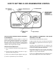
HOW TO SET TIME CLOCK REGENERATION CONTROL HOW TO SET DAYS ON WHICH WATER SOFTENER IS TO REGENERATE: HOW TO MANUALLY REGENERATE YOUR WATER SOFTENER AT ANY TIME. Rotate the skipper wheel until the number "1" is at the red pointer. Set the days that regeneration is to occur by sliding tabs on the skipper wheel outward to expose trip fingers. Each tab is one day. Finger at red pointer is tonight. Moving clockwise from the red pointer, extend or retract fingers to obtain the desired regeneration schedule.
HOW TO SET METER REGENERATION CONTROL TYPICAL RESIDENTIAL APPLICATION: To program, just set the time, set the hardness and it automatically monitors system needs and regenerates only when necessary. To set time of day, press red time set button and turn 24-hour gear until present time of day is opposite "time of day arrow.
SECTION 4: SERVICE INSTRUCTIONS PROBLEM 1. 2. 3. CAUSE Hard water, (unit NOT using salt; liquid level in brine tank NOT too high). A. Hard water, (unit using salt; liquid level in brine tank NOT too high). Liquid level in brine tank TOO high. SOLUTION A. B. C. D. E. Electrical service to unit interrupted. Timer not working. Timer improperly set. Safety brine valve not opening. Salt "bridged" in brine tank. A. B. Bypass open. Timer improperly set. A. B. C. D. No salt in brine tank.
SECTION 5: SPECIFICATIONS AND OPERATING DATA TIMER INITIATED MODELS: ITEM NS0751 NS1001 NS1501 NS2001 NS2501 NLS0501 NLS0751 NLS1001 TWO TANK System Style: SPACEMAKER Nominal Media Volume, cu. ft. 0.75 1.0 1.5 2.0 2.5 0.5 0.75 1.0 Salt dosage, lbs.: Factory Setting Maximum Setting 6.0 12.0 6.0 15.0 9.0 24.0 12.0 24.0 15.0 24.0 6.0 8.0 6.0 12.0 6.0 15.
METER INITIATED MODELS: ITEM NSM0751 NSM1001 NSM1501 NSM2001 NSM2501 NLSM0751 NLSM1001 System Style: TWO TANK SPACEMAKER Nominal Media Volume, cu. ft. 0.75 1.0 1.5 2.0 2.5 0.75 1.0 Salt dosage, lbs.: Factory Setting (1) Maximum Setting 6.0 12.0 6.0 15.0 9.0 24.0 12.0 24.0 15.0 24.0 6.0 12.0 6.0 15.
SECTION 6: PARTS COMPONENT PARTS LIST TWO TANK MODELS (NS & NSM SERIES) REF NO. 1 DESCRIPTION NS0751 NSM0751 NS1001 NSM1001 Control Valve, Time Clock Initiation, with Cover, less Bypass (NS Series) N100120-5R N100150-5W Control Valve, Meter Initiation, with Cover, less Bypass (NSM Series) N12J120-5R N12J150-5W 2 3 4 5 6 7 Adapter Assy., Flg-Thrd (Incl. Ref. 3) O-Ring Clamp Assy. (Incl. Ref. 5) Latch, Clamp Media Tank w/Base (Incl. Ref.
COMPONENT PARTS LIST SPACE-MAKER MODELS (NLS & NLSM SERIES) REF NO.
CONTROL VALVE - 12 DAY TIMER 6-3
ONLY THOSE PARTS CIRCLED IN DRAWING AND/OR LISTED BELOW ARE STOCK ITEMS ALL OTHERS ARE SPECIAL ORDER, NON-RETURNABLE PARTS LIST - 12 DAY TIMER REF. PART NO. DESCRIPTION A B C D E F G H J K L 60353-13 14381X 13010X 13168-36X 14449-00X 60102-00 60125 60084-50X 60022-50 10090X 60049/18706X 60049/18706-02X Power Head Assy., Complete, L/Cover, NS/NLS Series (Incl. Ref. Items 2-37) Skipper Wheel Assy. (Incl. Ref. Items 4-10) 24-Hour Gear Assy. (Incl. Ref. Items 11-17) Brine Cam Assy. 6-36 lb. Salt (Incl.
CONTROL VALVE - METER INITIATED 6-5
ONLY THOSE PARTS CIRCLED IN DRAWING AND/OR LISTED BELOW ARE STOCK ITEMS ALL OTHERS ARE SPECIAL ORDER, NON-RETURNABLE PARTS LIST - METER TIMER REF. PART NO. DESCRIPTION A B C D E F G H J K L 60354-13 14039X 13010X 13168-36X 14449-00X 60102-00 60125 60084-50X 60022-50 60086 60049/18706X 60049/18706-02X Power Head Assy., Complete, L/Cover, NSM/NLSM Series (Incl. Ref. Items 2-40) Program Wheel Assy. (Incl. Ref. Items 4-7, Specify "K" Label or Model) 24-Hour Gear Assy. (Incl. Ref.
SECTION 7: MAINTENANCE REPLENISHMENT OF SALT SUPPLY: PREVENTING IRON-FOULING OF MINERAL BED: The salt storage capacity of the brine tank is approximately 160 lbs. During each regeneration a specific amount of salt is consumed, thus requiring its periodic replenishment (the frequency is dependent on the regeneration schedule). Always replenish salt before the supply is exhausted to assure a continuous supply of softened water.
FIVE YEAR LIMITED WARRANTY GENERAL CONDITIONS WARRANTY POLICY Damage to any part of this water conditioner because of misuse, misapplication, neglect, alteration, accident, installation or operation contrary to our printed instructions, or damage caused by freezing, flood, vacuum, fire or Act of God, is not covered by this warranty. In all such cases, regular parts and service charges will apply.