SQC Series Owner's Manual This Manual is for the Installation, Operation, and Maintenance of the WATER FACTORY SYSTEMS® SQC Series Reverse Osmosis (RO) Drinking Water Appliance © 2001 CUNO Incorporated 98-880040 1101
INTRODUCTION This manual explains the installation, operation and maintenance of the Water Factory Systems® SQC Series Reverse Osmosis (RO) Drinking Water Appliances. Please read each section of this manual carefully. The specific model chosen should be appropriate for the local water conditions and the customer's needs. Check the Performance Data Sheet for the performance characteristics and the conditions of use.
I. Installation Instructions A. DETERMINE THE APPLIANCE LOCATIONS B. PREPARE THE AREA FOR INSTALLATION The appliance can be located under a sink or in a basement depending on space availability and the customer's preference. If a basement installation is selected, additional tubing, hardware and fittings may be needed and a hole will have to be made from inside the cabinet, through the floor, to the basement.
C. PREPARE THE APPLIANCE FOR INSTALLATION Procedure: 1) Center punch a small indent at the center of the desired faucet location. 2) Slowly drill the required pilot hole for the chassis punch. 3) Set up the chassis punch per the instructions and tighten the nut to cut the desired hole size. 4) Clean up all sharp edges with a file if necessary. Open the shipping carton and remove the components. Check to see that all of the installation parts are present.
E. MOUNT THE FAUCET 3) Undercounter installations generally require that the faucet's built-in air gap be used. In basement installations, the built-in air gap does not have to be used if one is provided elsewhere on the drain line. 4) 5) For Basement Installations Without An Air Gap Module See Installation Instructions O. 6) IMPORTANT: The Uniform Plumbing Code dictates that there must be an air gap between the RO reject line and the waste drain.
F. INSTALL THE FEED WATER TAPPING VALVE AND TUBING IMPORTANT: Some local plumbing codes may prohibit the use of saddle-type valves and/or drain connections. States prohibiting the use of saddle valves are Alaska, Delaware, Idaho, Kentucky, Massachusetts, Michigan, Minnesota, New Hampshire, North Dakota, Ohio, and South Dakota. Check your local plumbing codes for any restrictions that apply. Massachusetts CMR 248 strictly prohibits the use of saddle-type valves.
G. PREFILL AND SANITIZE THE STORAGE TANK The drain saddle should always be installed above (before) the trap and on the vertical or horizontal tailpiece. Never install the drain saddle close to the outlet of a garbage disposal because plugging of the RO drain line may occur. (See Fig. 4) Prefilling the storage tank is always recommended so that there is pressure to check for leaks as well as sufficient water to flush the carbon postfilter.
I. INSTALL THE PURIFICATION ASSEMBLY AND STORAGE TANK 5) 6) For Basement Installation See Installation Instructions O. Undercounter Installation: The purification assembly is usually mounted to the right or the left side wall inside of the sink cabinet, taking into consideration the space available and the tank location. Generally, the storage tank is placed in the rear of the sink cabinet while the purification assembly is positioned toward the front for filter cartridge accessibility.
‘Push-In’ Tubing Connector This product is outfitted with user friendly ‘Push In’ connectors. Proper use of the connectors is shown in the diagrams. It is most important that the tubing selected for use with these connectors be of high quality, exact size and roundness, and with no surface nicks or scratches. If it is necessary to cut the tubing, use a plastic tubing cutter or sharp razor knife. Make a clean square cut. Should a leak occur at a ‘Push-In’ connector, the cause is usually defective tubing.
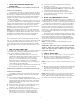
Faucet without Air Gap (FL 3/8” Blue Tubing* For refrigerator icemaker or water dispenser hookup, tee into tubing OO R) Feedwater Tapping Valve Storage Tank Valve Red SFC Tubing Cold Water Supply Pipe 3/8” Yellow Tubing* 1/4” Orange Tubing Storage Tank** 1/4” green tubing Purification Assembly (Ba sem en Laundry Sink, Standpipe or Floor Drain tF loo Air Gap Device (e.g.
O. APPENDIX FOR BASEMENT INSTALLATIONS MAKE THE TUBING CONNECTIONS 1) A proper length of the 1/4" orange feed water tubing should already have been connected to the feed water tapping valve. Route it through the large opening in the bottom of the metal bracket and loop it back to the "FEED" connection on the purification assembly. 2) Thread the taped 3/8" x 1/4" elbow fitting into the tank valve. Do not over tighten. 3) Connect a longer length of 3/8" blue tubing (not included) to the faucet adapter.
P. INSTALLATION TROUBLESHOOTING Problem: Water leaks from air gap module opening. Causes: The drain line tubing is looped, kinked, or has a low spot. • The drain line is blocked or the drain hole is not drilled • through completely. Air is locked in the air gap outlet. • There is excessive RO reject flow. • Solutions: Trim any excess tubing to obtain a short, "straight-shot" to • the drain.
II. Operation & Maintenance Instructions A. IMPORTANT WATER QUALITY ASSURANCE REQUIREMENTS When to Replace the Carbon Postfilter Cartridge • If the filter is being used to control tastes and odors, replace it every year. • If the filter is being used to reduce chloramines, change it every six months. For critical applications such as aquariums, base the filter change on periodic chloramine (combined chlorine) tests.
When to Replace the RO Membrane Cartridge • As determined by a built-in percent rejection (PR) monitor: The monitor is factory preset so that a green light will be displayed when the water quality is good, and a red or yellow light indicates that cartridge replacement may be necessary. If a red or yellow light is displayed, the faucet should be opened and the storage tank trained. After it has refilled, check the water quality again.
1) 2) 3) 4) 5) 6) 7) 8) Close the feed water tapping valve and lift up on the faucet handle to empty the water in the storage tank. It should feel light when empty. Shut off the faucet and close the valve at the top of tank. Disconnect the 3/8" yellow tubing from the back for the purification assembly. (Refer to Fig. 6 on the use of the special "Push-In" connectors.) Remove the tank from its location and drain it into the sink by turning it upside down and opening the valve.
CUNO Incorporated 400 Research Parkway Meriden, CT 06450, U.S.A. Toll Free: 1-800-733-1199 Worldwide: 203-237-5541 Fax: 203-238-8701 www.waterfactorysystems.com • www.cuno.