
User Manual

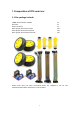


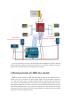
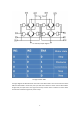

Table Of Contents
6
1. Front wheel motor forwards, rear wheel motor backwards.
2. There is a raised dots on each motors, and all of them should be placed toward the same
direction(on the left when facing the car).You can test the direction of rotation of the motors first
before installing them.
Note: We recommend that novice players assemble the DC motor in strict accordance with the
direction of our experimental prototype, due to we provided a program corresponding to the
direction of rotation of the motor, which can realize the car's forward, obstacle avoidance and
tracking functions. If you are familiar with the operating principles and procedures of the smart
car, you can modify the corresponding code according to your favorite installation method, and
let the smart car work according to your installation.
2.2.Wiring method
(1) Connect the L298N drive module to the power supply:
L298N +12V --- 2Pcs 14500 3.7V Power +
L298N GND --- 2Pcs 14500 3.7V Power -
(2) Connect the L298N drive module to the UNO R3 main board:
L298N 5V ------ UNO R3 5V
L298N GND --- UNO R3 GND
L298N ENA ----UNO R3 Pin 10
L298N IN1 -----UNO R3 Pin 7
L298N IN2 -----UNO R3 Pin 6
L298N IN3 -----UNO R3 Pin 5
L298N IN4 -----UNO R3 Pin 4
L298N ENB --- UNO R3 Pin 9
(3) Connect the ultrasonic module to the UNO R3 main board:
Vcc --- UNO R3 5V
Trig --- UNO R3 Pin 12
Echo --- UNO R3 Pin 13
GND --- UNO R3 GND
(4) Connect the tracking module 1 to the UNO R3 main board:
Vcc --- UNO R3 5V
GND --- UNO R3 GND
S --- UNO R3 Pin 8
(5) Connect the tracking module 2 to the UNO R3 main board:
Vcc --- UNO R3 5V
GND --- UNO R3 GND
S --- UNO R3 Pin 2
Note: If you use the code provided by us to drive the tracking module to work, please
interchange the wiring of the "S" interface on the two tracking modules after connecting the
wires according to the above wiring method.