
Installation Guide


HAVING INSTALLATION QUESTIONS? CALL TECHNICAL SUPPORT AT 1-877-287-8634
INSTALLATION STEPS
PERIODICALLY CHECK THIS RECEIVER HITCH TO ENSURE THAT ALL FASTENERS
ARE TIGHT AND THAT ALL STRUCTURAL COMPONENTS ARE SOUND.
Curt Manufacturing LLC., warrants this product to be free of defects in material and/or workmanship at the time of retail purchase by the original purchaser. If the product is found to be defective,
Curt Manufacturing LLC., may repair or replace the product, at their option, when the product is returned, prepaid, with proof of purchase. Alteration to, misuse of, or improper installation of
this product voids the warranty. Curt Manufacturing LLC.'s liability is limited to repair or replacement of products found to be defective, and specifically excludes liability for incidental or
consequential loss or damage.
CADILLAC ATS
5/17/2016
11311
PAGE 2 of 2
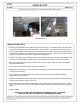
1. Remove (14) screws that secure plastic fascia to bottom of vehicle. This will allow fascia to be pulled away
from exhaust, and allow heat shield to be removed. Coupe models: remove fasteners with a 7mm socket.
2. Lower exhaust by first removing (2) bolts on each side from the end of the vehicle frame rails that secure the
exhaust hanger brackets. Remove brackets from hanger pegs on muffler. Then remove the rubber exhaust
hangers, (4) places forward of mufflers, (3) places on Coupe models.
3. It may be necessary to remove support strap to allow exhaust to hang lower and allow heat shield to be fully
removed. It will be necessary to gently pull fascia downward to allow muffler pegs to be below fascia.
4. Remove heat shield by removing (8) nuts which secure it to the vehicle. Retain (6) nuts for reinstallation
after heat shield trimming.
5. Cut off stud from each frame rail that secured the heat shield.
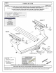
6. Mark heat shield as shown and trim to allow access to both frame rails. Reattach trimmed heat shield using
(6) nuts removed in Step 4.
7. Trim vehicle fascia as shown on each side of the vehicle to allow for hitch side plate reinstallation,
approximately 1-3/8" each side.
8. Fishwire 1/2" carriage bolts and spacer blocks up through slots in vehicle frame and down through attaching
holes in hitch side plates, 2 places, each side.
9. Raise hitch and hitch into position simultaneously, being careful not to push bolts back into frame. Secure
with 1/2" flange hex nuts. Torque all 1/2" hardware to 110 lb-ft. Reattach exhaust support strap if removed in
Step 3.
10. Install complete.
TRIM DIAGRAM