
Installation Guide


Parts List
DESCRIPTIONPART NUMBERQTYITEM
7/16" FISHWIRE7_16 FISHWIRE41
.250 x .88 x 2.25" SQUARE HOLE SPACERCM-SP2
42
CARRIAGE BOLT7/16-14 x 1 1/443
HEX FLANGE NUT7/16-1444
GROSS LOAD CAPACITY WHEN USED AS A WEIGHT CARRYING HITCH: LBS. TRAILER WEIGHT & LBS. TONGUE WEIGHT.
WARNING: ALL NON-TRAILER (WHEEL-LESS) LOADS APPLIED TO THIS PRODUCT MUST BE SUPPORTED BY 18050 STABILIZING STRAPS.
WARNING: ** FAILURE TO PROPERLY SUPPORT NON-TRAILER LOADS WILL VOID PRODUCT WARRANTY **
WARNING: *** DO NOT EXCEED VEHICLE MANUFACTURER'S RECOMMENDED TOWING CAPACITY ***
FOR MORE INFORMATION LOG ONTO WWW.CURTMFG.COM
HAVING INSTALLATION QUESTIONS? CALL TECHNICAL SUPPORT AT 1-800-798-0813
HITCH WEIGHT: LBS.
INSTALL TIME
PROFESSIONAL: MINUTES
NOVICE (DIY): MINUTES
INSTALL NOTES:
INSTALLATION STEPS
PERIODICALLY CHECK THIS RECEIVER HITCH TO ENSURE THAT ALL FASTENERS
ARE TIGHT AND THAT ALL STRUCTURAL COMPONENTS ARE SOUND.
CURT Manufacturing LLC., warrants this product to be free of defects in material and/or workmanship at the time of retail purchase by the original purchaser.
If the product is found to be defective, CURT Manufacturing LLC., may repair or replace the product, at their option, when the product is returned, prepaid,
with proof of purchase. Alteration to, misuse of, or improper installation of this product voids the warranty. CURT Manufacturing LLC.'s liability is limited to
repair or replacement of products found to be defective, and specifically excludes liability for incidental or consequential loss or damage.
This product complies with safety specifications and requirements for connecting devices and towing systems of the state of New York, V.E.S.C.Regulation V-5 and SAE J684.
2,000 200
26
30
NISSAN KICKS
2/8/2019
11563
60
Scan
for more
information
3
2
4
1
-NO DRILL
-TRIM HEAT SHIELD
-TEMPORARILY REMOVE PARTS
1. Locate on driver side frame rail and temporarily remove emmissions canister by removing (1) fastener using
10mm socket.
NOTE: If present remove frame rail plug, to access rear mounting point on driver side.
2. On Passenger side lower exhasut by removing (2) exhaust isolators, using isolator removal digram, to expose
heat shield. Remove heat shield by removing 4 speed nuts.
3. Trim heat shield as shown in the Heat Shield Trim Diagram.
NOTE: All dimensoins are approviamate, confirm fit prior to trimming.
4. Enlarge forward most attachment hole using a die grinder. Use hole enlargement diagram as a reference.
5. Fishwire 7/16 hardware through enlarged hole and out rear most attachment hole. Use fishwire diagram as a
reference.
6. Reverse fishwire 7/16 hardware through enlarged hole. Use reverse fishwire diagram as a reference.
7. Reinstall trimmed heat shield and raise hitch into position.
8. Torque all 7/16 hardware to 59 ft-lbs. Reinstall emmissions canister, raise exhaust into vehicle position.
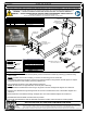
PASSENGER SIDE
FRAME RAIL
DRIVER SIDE
FRAME RAIL
FORWARD MOST
ATTACHMENT HOLE
(BOTH SIDES)
REAR MOST
ATTACHMNET HOLE
(BOTH SIDES)
TOOLS REQUIRED
RATCHET
TORQUE WRENCH
8" SOCKET EXTENSION
10mm, 13mm, 11/16", 15/16" SOCKETS
PRY TOOL
AVIATION SHEERS
DIE GRINDER
SAFETY GLASSES
DESIGNED FOR USE WITH
BALL MOUNT #45521
EURO MOUNT
OPTION AVAILABLE
#45571 (1 7/8" BALL)
#45572 (2" BALL)
HEAT SHIELD
TRIM DIAGRAM
1 ADDED HEAT TRIM SHIELD DIAGRAM 2/8/2019 DAM
REVISION HISTORY
REV DESCRIPTION DATE APPROVED