
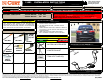
Installation Guide

GROSS LOAD CAPACITY WHEN USED AS A WEIGHT CARRYING HITCH: LBS. TRAILER WEIGHT & LBS. TONGUE WEIGHT.
***DO NOT EXCEED VEHICLE MANUFACTURER'S RECOMMENDED TOWING CAPACITY.***
WARNING: ALL NON-TRAILER LOADS APPLIED TO THIS PRODUCT MUST BE SUPPORTED BY AUXILIARY STABILIZING STRAPS.
** FAILURE TO PROPERLY SUPPORT NON-TRAILER LOADS WILL VOID PRODUCT WARRANTY**
HAVING INSTALLATION QUESTIONS? CALL TECHNICAL SUPPORT AT 1-877-287-8634
INSTALLATION STEPS
PERIODICALLY CHECK THIS RECEIVER HITCH TO ENSURE THAT ALL FASTENERS
ARE TIGHT AND THAT ALL STRUCTURAL COMPONENTS ARE SOUND.
Curt Manufacturing Inc., warrants this product to be free of defects in material and/or workmanship at the time of retail purchase by the original purchaser. If the product is found to be defective,
Curt Manufacturing Inc., may repair or replace the product, at their option, when the product is returned, prepaid, with proof of purchase. Alteration to, misuse of, or improper installation of
this product voids the warranty. Curt Manufacturing Inc.'s liability is limited to repair or replacement of products found to be defective, and specifically excludes liability for incidental or
consequential loss or damage.
2,000 200
HONDA ACCORD (ALL)
11681
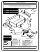
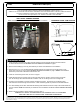
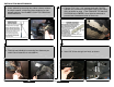
1. Lower exhaust by removing two rubber exhaust isolators for single exhaust vehicles and three isolators
for dual exhaust vehicles. See RUBBER ISOLATOR REMOVAL DIAGRAM on page 1.
2. Remove heat shield(s) by removing four fasteners per shield. Save fasteners for reinstallation.
3. Fishwire 7/16"-14 x 1 1/4" carriage bolts with CM-SP2 spacers into poistion through access holes in both
frame rails, as shown on page 1. See FISHWIRE TECHNIQUE DIAGRAM on page 1. NOTE: Leave fishwires
attached to prevent loss of hardware inside of frame rail.
4. Insert 3/8" U-bolt through tow hook, as shown on page 1.
5. Insert fishwires through mounting holes in hitch and raise hitch into position. Secure it to the U-bolt with
3/8"-16 hex flange nuts. Remove fishwires and attach 7/16"-14 hex flange nuts to the carriage bolts.
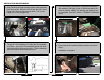
6. Torque all 7/16" hardware to 70 ft-lbs and 3/8" hardware to 45 ft-lbs. (If present) Trim underbody panel
then slide hitch bracket through trimmed section. Raise underbody panel into position and reinstall fasteners.
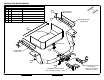
7. Trim heat shield(s) around hitch. Reinstall heat shield(s) with hardware removed in Step 2. Bend heat sheild over
hitch as needed. NOTE: One fastener per shield will not be reinstalled. See HEAT SHIELD TRIMMING DIAGRAM
above.
8. Raise exhaust and reattach rubber isolators removed in Step 1.
INSTALLED HITCH POSITION
4 in
3 in
4 in
HEAT SHIELD TRIMMING DIAGRAM
NOTE: TRIM DIMENSIONS ARE APPROXIMATE, CONFIRM FIT PRIOR TO TRIMMING.
VEHICLE BUMPER
UNDERBODY PANEL TRIM DIAGRAM