
Installation Manual


Table Of Contents
HOLE ENLARGEMENT
DIAGRAM
HAVING INSTALLATION QUESTIONS? CALL TECHNICAL SUPPORT AT 1-800-798-0813
INSTALLATION STEPS
PERIODICALLY CHECK THIS RECEIVER HITCH TO ENSURE THAT ALL FASTENERS
ARE TIGHT AND THAT ALL STRUCTURAL COMPONENTS ARE SOUND.
CURT Manufacturing LLC., warrants this product to be free of defects in material and/or workmanship at the time of retail purchase by the original purchaser. If the product is found to be defective,
CURT Manufacturing LLC., may repair or replace the product, at their option, when the product is returned, prepaid, with proof of purchase. Alteration to, misuse of, or improper installation of this
product voids the warranty. CURT Manufacturing LLC.'s liability is limited to repair or replacement of products found to be defective, and specifically excludes liability for incidental or consequential
loss or damage.
SUBARU OUTBACK
2/20/2015
13206
PAGE 2 of 2
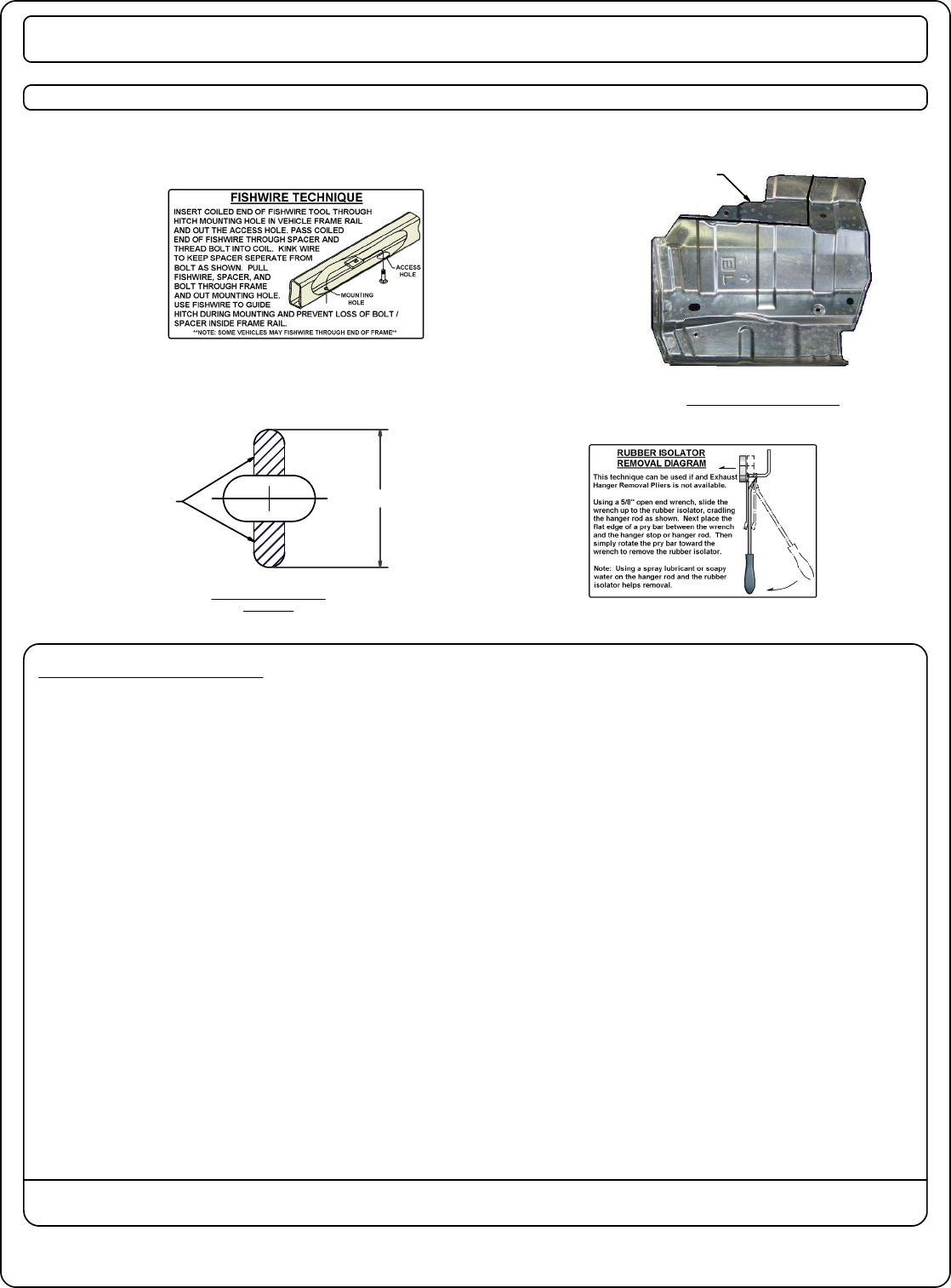
1. Lower the exhaust by removing the (3) rearmost rubber exhaust isolators from the frame mounted
hangers. Note: Support the exhaust during installation to prevent damage.
(See Rubber Isolator Removal Diagram.)
2. Remove the muffler heat shield and trim to clear the mounting plate. (See Heat Shield Trim Diagram.)
3. Remove the (2) rubber plugs in each frame rail. Enlarge the forwardmost hole on each frame rail to allow
the carriage bolt and spacer to be inserted into the frame rail. (See Hole Enlargement Diagram.)
4. Fishwire a carriage bolt and spacer into the rearmost hole in each frame rail as shown.
(See Fishwire Technique.)
5. Raise the hitch into position. Center the hitch on the vehicle and loosely secure the hitch to the
vehicle, remove fishwire, and loosely secure the hitch with hex flange nuts as shown.
6. Mark and drill the forwardmost holes in the frame rail using the hitch as your template.
7. Fishwire a carriage bolt and spacer into each drilled hole and secure the hitch with a hex flange nut
as shown.
8. Torque all 1/2" hardware to 110 ft-lbs.
9. Reinstall the heat shield, raise the exhaust and reinstall the rubber isolators.
HEAT SHIELD TRIM DIAGRAM
TRIM ALONG
BEND LINE
1.125 in
REMOVE