
Installation Guide


HAVING INSTALLATION QUESTIONS? CALL TECHNICAL SUPPORT AT 1-877-287-8634
INSTALLATION STEPS
PERIODICALLY CHECK THIS RECEIVER HITCH TO ENSURE THAT ALL FASTENERS
ARE TIGHT AND THAT ALL STRUCTURAL COMPONENTS ARE SOUND.
CURT Manufacturing LLC., warrants this product to be free of defects in material and/or workmanship at the time of retail purchase by the original purchaser. If the product is found to be defective, CURT
Manufacturing LLC., may repair or replace the product, at their option, when the product is returned, prepaid, with proof of purchase. Alteration to, misuse of, or improper installation of this product voids the
warranty. CURT Manufacturing LLC.'s liability is limited to repair or replacement of products found to be defective, and specifically excludes liability for incidental or consequential loss or damage.
This product complies with safety specifications and requirements for connecting devices and towing systems of the state of New York, V.E.S.C.Regulation V-5 and SAE J684.
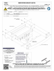
MERCEDES-BENZ GLE350
10/19/2016
13294
PAGE 2 of 2
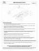
1. On the fascia tab bracket, locate and remove (2) screws from rear fascia and (1) nut located on top of bracket
using 10mm socket. Remove bracket and return to owner.
2. Lower exhaust by removing rubber isolator from hanger attached to vehicle frame, (1) on each side. Support
exhaust to prevent damage. (See Rubber Isolator Removal Diagram)
NOTE: Removing exhaust tips using T-40 socket may ease installation.
3. Locate on heat shield and remove (6) nuts using 8mm socket, (2) screws using E-10 socket, and (2) screws
using 10mm socket. Remove heat shield and set aside for reinstallation.
4. Remove trunk liner guard using T-30 socket to remove screw. Gently unclip trunk liner guard and remove trunk
contents to expose bumper beam nut inside vehicle. Set aside trunk contents and trunk liner guard for
reinstallation.
5. Inside trunk locate and remove bumper beam nuts, (2) on each side, using 16mm socket.
NOTE: Removing trunk liner bin on driver side may ease installation.
6. Under vehicle locate and remove bumper beam nuts, (2) on each side, using 16mm socket.
7. After all (8) bumper beam nuts have been removed, with rear fascia still attached, push bumper beam away
from vehicle to sandwich hitch between bumper beam and vehicle. Loosely secure vehicle hardware.
NOTE: Completing one side at a time may ease installation.
8. Secure provided fascia tab brackets to hitch main body plates, with 1/4" hardware, using 7/16" socket and 7/16"
boxed end wrench. Align and secure (2) center fascia tabs by pushing nylon retainer clips into fascia tab brackets.
9. Torque all 1/4" hardware to 10 ft-lbs and all M10 hardware to 45 ft-lbs. Reinstall following steps 2 - 4 in
reverse order. Installation complete.