
Installation Guide
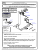

HITCH SHOWN IN PROPER POSITION
Parts List
DESCRIPTION
PART NUMBER
QTY
ITEM
SPACER PLATE .500" A-36 H.R.CM-13375-SP
41
NUT, SER-FLANGE,1/2-13 UNC,GRD8,YZ
20-0006282
.250 x 1.38 x 1.50" ROUND HOLE SPACERCM-SP25
23
WASHER,FLAT,1/2,YZ
30-0013384
HHCS,1/2-13 UNC,5,GRD8,YZ
10-102948
5
GROSS LOAD CAPACITY WHEN USED AS A WEIGHT CARRYING HITCH: LBS. TRAILER WEIGHT & LBS. TONGUE WEIGHT.
GROSS LOAD CAPACITY WHEN USED AS A WEIGHT DISTRIBUTION HITCH: LBS. TRAILER WEIGHT & LBS. TONGUE WEIGHT
***DO NOT EXCEED VEHICLE MANUFACTURER'S RECOMMENDED TOWING CAPACITY.***
HAVING INSTALLATION QUESTIONS? CALL TECHNICAL SUPPORT AT 877-287-8634
INSTALLATION STEPS
PERIODICALLY CHECK THIS RECEIVER HITCH TO ENSURE THAT ALL FASTENERS
ARE TIGHT AND THAT ALL STRUCTURAL COMPONENTS ARE SOUND.
Curt Manufacturing Inc., warrants this product to be free of defects in material and/or workmanship at the time of retail purchase by the original purchaser. If the product is found to be defective,
Curt Manufacturing Inc., may repair or replace the product, at their option, when the product is returned, prepaid, with proof of purchase. Alteration to, misuse of, or improper installation of
this product voids the warranty. Curt Manufacturing Inc.'s liability is limited to repair or replacement of products found to be defective, and specifically excludes liability for incidental or
consequential loss or damage.
5,000 500
7,500
750
DODGE SPRINTER 3500 VAN (ALL)
w/FACTORY STEP BUMPER 144" WHEEL BASE
8/12/2020
13375
60
41
30
HITCH WEIGHT: LBS.
INSTALL TIME
PROFESSIONAL: MINUTES
NOVICE (DIY): MINUTES
INSTALL NOTES:
1. Lower spare tire for ease of installation.
2. Remove (6) existing bolts and nuts from bumper mounting brackets and return to owner.
NOTE: Support bumper as necessary to prevent from falling.
3. Install 1/2" X 5" hex head bolts and 1/2" flat washers from the inside of the frame rail through existing holes
and out step bumper bracket holes as shown.
4. Install SP25 spacer over the upper forward most bolt, each side. Install (2) 1/2" spacer plates over the
bolts on each side of vehicle as shown.
NOTE: For ease of installation push hex bolts back so the threaded portion is flush with the 1/2" spacer plates.
5. Raise hitch into position by sliding the hitch side plates over the outside of the bumper mounting brackets
and aligning the holes as shown. Push the remainder of each bolt through the holes in the hitch side plates.
6. Secure hitch into position using 1/2" hex flange nut.
7. Torque all 1/2" hardware to 110 ft-lbs.
8. Reinstall spare tire.
DRIVER SIDE STEP
BUMPER BRACKET
DRIVER SIDE
FRAME RAIL
PASSENGER SIDE
STEP BUMPER BRACKET
PASSENGER SIDE
FRAME RAIL
2
1
3
4
5
-NO DRILLING REQUIRED
-LOWER SPARE TIRE
TOOLS REQUIRED
TORQUE WRENCH
RATCHET
18mm SOCKET
18mm WRENCH
3/4" SOCKET
3/4" WRENCH
STEP BUMPER
BRACKET
HITCH
FRAME RAIL
1
CHG TO GRADE 8 TORQUE SPECS
11/12/2012
AJP
2 UPDATED HARDWARE DESCRIPTIONS/NUMBERS 8/12/2020 CJW
REVISION HISTORY
REV DESCRIPTION DATE APPROVED