
Installation Manual
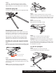
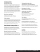

Top of coupler
to pavement
Trailer
coupler
height
Figure 2
Figure 3
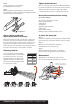
Figure 4
Figure 5
Upright
position
Inverted
position
Closest position to
height determined
as target
Measure trailer coupler height
Determine the 'target' uncoupled
ball height for the tow vehicle
Install shank, hitch head and ball
Line up the tow vehicle and trailer on level pavement, in
a straight position. Use the trailer tongue jack to level the
trailer. Measure the distance from pavement to the top
of the coupler socket and record here
Step 2
Position head assembly(#1) on shank (#2). Slide head
up or down to the nearest bolt hole alignment position
which corresponds with the target ball height determined
earlier. Mark the position on the shank. See Figure 4.
Tow vehicle's uncoupled ball height will be set higher
than the coupler height measured in Figure 2 to allow
for vehicle squat when coupled to trailer.
For passenger cars, add 1/8" for each 100 lbs. of tongue
weight. Record ball height
Step 1
Insert adjustable shank bar (#2) into receiver tube on tow
vehicle and secure with hitch pin & clip (#11). NOTE: To
obtain proper ball height on high ground clearance vehicles,
shank may be inverted as shown in Figure 3. If shank is used
in the inverted position, check for adequate ground clearance.
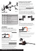
PARTS LIST
AS SEMBLY
3
2
10
11
11
6
4
8
9
7
5
Figure 1
Item# Qty Description
1 1 Hitch head
2 1 Adjustable shank bar
3 2 Spring trunnion bar
4 2 A-frame bracket
5 1 Snap-up handle
6 2 Head tilt spacer
7 1 Hex bolt, 3/4" - 10 x 5" long
8 2 Nylock nut, 3/4" - 10
9 1 Hex bolt, 3/4" - 10 x 4" long
10 2 Wire lock lynch pin
11 1 Hitch pin & clip, 5/8"
1
Measure the tow vehicle
Pick reference points on the front and rear bumper of the
towing vehicle. Measure and record height to pavement.
Front bumper to pavement
Rear bumper to pavement
For vehicles with air springs, air shocks or automatic
leveling systems only, check the vehicle's owners manual
or other instructions on these items. Unless otherwise
indicated, air springs and air shocks should be deflated
to their minimum recommended pressure before
assembling and adjusting the weight distributing hitch.
Step 4
Set the initial tilt position and loosely attach the hitch head
(#1) to the shank (#2) in the position determined in Step 3.
Step 5
For initial setup, place the head tilt spacers (#6)
into the position shown below in Figure 5.
Detail A
A
CURTMFG.COM • NEED ASSISTANCE? • 1.800.798.0813 • 17500-INS-RA • PAGE 2