
Installation Guide

CURTMFG.COM
•
PRODUCT SUPPORT: 877.287.8634
•
17501-INS-RD
•
12/08/2021
•
ECN8701
•
PAGE 5
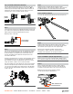
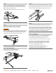
Step 12
Slide the L-support between the two captive support brackets as
shown. Set the bracket height closest to the spring bar position set
with the jack in Step 9. Install the second carriage bolt in the first
hole directly below the trailer A-frame.
With the L-bracket installed, tighten both nylock nuts to 25 lb-ft.
Step 15
Pry the spring bar onto the L-bracket by rotating the lift bar to vertical.
With the spring bar supported by the L-bracket, remove the lift handle.
Secure the spring bar by installing the retainer clip and cotter pin.
Step 13
Repeat Steps 10 through 12 with the second support
bracket on the opposite side of the trailer A-frame.
WARNING
Keep clear of the pivot path of all moving parts when there is tension
on the spring bar. Maintain control of the lift handle at all times when
raising or lowering the spring bar. Be sure that the locking clip and
cotter pin are in place once the spring bar is in position.
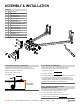
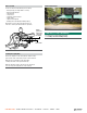
Step 14 - Raise the spring bars
Pull the spring bar out from the A-frame and
hook the lift bar into the L-bracket as shown.
Step 16
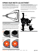
Check the vehicle height and adjust the spring bars if necessary.
With the spring bars secured, lower the jack to apply load to the hitch.
The vehicle should settle evenly. Remeasure the front and rear bumper
reference points. If the front has settled much more than the rear, lower
the L-brackets to reduce the load on the spring bars. The spring bars
should be nearly horizontal when correct height is achieved.
Step 17 - Tilt adjustment
If the L-support bracket in Step 12 is in the highest position and
you are unable to bring the rear of the vehicle to level when
the load is applied, you will need to adjust the head tilt.
Uncouple the trailer after removing the load from the spring bars.
Remove the top 3/4" hex bolt (#6) installed in Step 6 and add
washers or the long adjustment rod (#12) to increase head tilt.
Reinstall the 3/4" hex bolt and repeat Steps 14 -16 to ensure
the proper loaded ride height is achieved.
When the vehicle ride height is achieved, complete
the installation by fully torquing all hardware to 200 lb-ft,
including the 3/4" hex bolts (#6) installed in Step 7.