
Installation Guide

A B C
D E
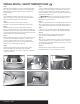
Step 1
Open the vehicle tailgate. Remove the scuff panel by pulling
out on the bottom and then up. Take care not to damage the
alignment tabs on the back. Remove the floor panels and
spare tire tray (A).
Step 2
Using a Phillips screwdriver, remove the rear cargo loops,
sliders and screws from the side rails so the driver side trim
panel can be pulled away from the vehicle (B).
Step 3
On the driver side, remove the fastener securing
the black styrofoam tray and carefully pry the tray out (C).
Step 4
On the driver side, remove the side pocket by carefully
prying out slowly until it pops out of the trim panel (D). On the
passenger side, find a small opening under the styrofoam pad
and reach under while prying up slowly on the passenger side
pocket until it pops out of the trim panel (E).
Step 5
On both sides of the vehicle, under the removed side pockets,
locate the vehicle taillight wiring harness connectors. The
connectors will be similar to those on the custom wiring
harness. Separate the connectors from the taillight housing
taking care not to damage the locking tabs.
Step 6
Starting on the passenger side, insert the custom wiring
harness end with green wire between the separated
connectors. Make sure the connectors are fully inserted with
locking tabs in place.
Step 7
Locate a suitable grounding point near the connector such as
an existing screw with nut in the vehicle frame or drill a 3/32"
pilot hole for the provided screw. The area should be free of
rust, dirt and paint. Secure the white ground wire using the ring
terminal and provided screw.
WARNING: Check for miscellaneous items that may be
hidden behind or under any surface before drilling to avoid
damage and / or personal injury.
Step 8
Route the custom wiring harness end with the yellow wire to the
driver side behind the removed scuff panels. Repeat steps 5-6
on the driver side using the harness end with the yellow wire.
Step 9
Locate a flat spot inside the vehicle, near the taillight. Adhere
the black converter box using the provided double-sided tape.
Step 10
Route the black power wire from the vehicle battery
as shown on the included CME-PCL-INS sheet.
Step 11
When in use, route the 4-flat to the center of the vehicle and out
of the trunk. When not in use, roll up and store in a convenient,
out of the way location inside the trunk. Secure any loose wires
with the provided cable ties.
Step 12
Reinstall all items removed during install. Install the
provided 4-flat dust cover to help prevent corrosion.
INSTALLATION
/
SAFETY INSTRUCTIONS
56026-INS-RA • PAGE 2