
Installation Guide
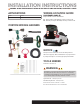

A B
H
C
D
G
E F
Step 1
Open the vehicle trunk. Remove all trunk floor coverings (A).
Remove the foam cargo trays on top of the spare tire (B).
Step 2
Remove the two plastic fasteners securing the rear scuff panel
(C). Remove the scuff panel by pulling up (D). Take care not to
damage the alignment tabs on the back.
Step 3
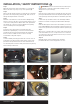
Pull back on the felt liner to locate the vehicle taillight wiring
harness connectors (E). The connectors will be similar to those
on the custom wiring harness. On the driver side, separate the
grey and brown connectors from the taillight housing taking
care not to damage the locking tabs (F,G).
Step 4
Insert the custom wiring harness end with yellow wire
between the separated grey connectors. Insert the harness
end with the brown and red wires between the separated
brown connectors. Make sure the connectors are fully
inserted with locking tabs in place.
Step 5
Locate a suitable grounding point near the connector such as
an existing screw with nut in the vehicle frame or drill a 3/32"
pilot hole for the provided screw. The area should be free of
rust, dirt and paint. Secure the white ground wire using the ring
terminal and provided screw.
WARNING: Check for miscellaneous items that may be
hidden behind or under any surface before drilling to avoid
damage and / or personal injury.
Step 6
Route the custom wiring harness end with the green wire to the
passenger side behind the removed scuff panel. Repeat steps 2-4
on the passenger side using the harness end with the green wire.
Step 7
Locate a flat spot inside the vehicle, near the taillight. Adhere
the black converter box using the provided double-sided tape.
Step 8
Route the black power wire from the vehicle battery as shown on
the included CME-PCL-INS sheet. When routing the wire into the
trunk use the grommets in the trunk pan under the spare tire (H).
Step 9
When in use, route the 4-flat to the center of the vehicle and out
of the trunk. When not in use, roll up and store in a convenient,
out of the way location inside the trunk. Secure any loose wires
with the provided cable ties.
Step 10
Reinstall all items removed during install. Install the
provided 4-flat dust cover to help prevent corrosion.
INSTALLATION
/
SAFETY INSTRUCTIONS
56139-INS-RA • PAGE 2