
Installation Guide


I
L
INSTALLATION
/
SAFETY INSTRUCTIONS
J
M
K
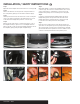
Step 8
Starting on the driver side, use the pry tool to remove the
protective caps covering the fasteners below the taillight (I).
Remove the three fasteners securing the rear fascia. Repeat
on the passenger side of the vehicle.
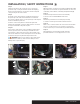
Step 9
Route the custom wiring harness end with the green wire to
the passenger side of the vehicle behind the loosened rear
fascia (J,K,L). Repeat steps 3-5 on the passenger side using the
harness end with the green wire.
Insert the custom wiring harness end with the green wire
between the separated connectors. Make sure the connectors
are fully inserted with locking tabs in place.
Step 10
In the interior of the vehicle, locate a suitable grounding point
near the grommet such as an existing screw with nut in the
vehicle frame or drill a 3/32" pilot hole for the provided screw.
The area should be free of rust, dirt and paint. Secure the white
ground wire using the ring terminal and provided screw.
WARNING: Check for miscellaneous items that may be
hidden behind or under any surface before drilling to avoid
damage and / or personal injury.
Step 11
Adhere the black converter box using the provided double-sided
tape. Failure to mount the box in a protected area can cause loss
of warranty, product failure, overheating and potential fire (M).
Step 12
Route the black power wire from the vehicle battery
as shown on the included CME-PCL-INS sheet.
Step 13
Reseat the grommet and use sealant (not provided)
to seal the cut in the grommet and around all the wires.
Step 14
When in use, route the 4-flat to the center of the vehicle. When
not in use, roll up and store in a convenient, out of the way
location. Secure any loose wires with the provided cable ties.
Step 15
Reinstall all items removed during install. Install the
provided 4-flat dust cover to help prevent corrosion.
PAGE 3 • 56181-INS-RB