
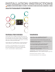
Installation Guide

A B C
Step 1
Locate vehicle taillight wiring.
Step 2
Using a 24V capable test lamp, probe or multi-meter,
identify the corresponding wires in the harness for the
left turn, right turn, taillights and brake lights.
Step 3
Locate vehicle battery and disconnect
the negative battery terminal.
Step 4
Using snap locks, attach the input wires of the taillight converter
to the corresponding vehicle harness wires identified in Step 2.
Refer to photos A, B and C to install the snap locks.
Green wire: Right-turn circuit
Red wire: Brake-light circuit
Yellow wire: Left-turn circuit
Brown wire: Taillight circuit
Step 5
Locate a clean, accessible mounting location for the black
converter box. If mounting outside of the vehicle, find a clean
surface that is out of the path of spray and debris from the
rear wheels and road surface.
Step 6
Locate a suitable grounding point near the connector such
as an existing screw with nut in the vehicle frame or drill a 3/32"
pilot hole for the provided screw. The area should be free of
rust, dirt and paint. Secure the white ground wire using a
ring terminal and screw.
Step 7
Secure the converter wires to the vehicle using cable ties.
Reinstall all items removed during install and reconnect
negative battery terminal.
INSTALLATION
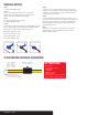
CONVERTER WIRING DIAGRAM
If using the converter as a
powered module for a
two-wire system, the red
brake wire must be grounded
ATTENTION!
Not Included:
* Self-tapping screws
* Snap locks
* Cable ties
* Butt connectors
* Ring terminals
The converter is only to be used on
24 volt negative ground systems
Green - Right turn
Red - Brake
Yellow - Left turn
Brown - Taillight
White - Ground
Mount converter using
double-sided tape
Converter
56424-INS-RA • PAGE 2