
Installation Guide

convertidor.
convertisseur,
10/1/2010
NOTE:
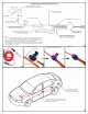
Figure 1 shows typical vehicle locations to access the
wires you will need to provide the required signals to
your converter. Page 2 provides detail for converter
connections and typical routing of the converter power
wire from the vehicle’s battery to the converter. Refer
to these illustrations as you read through the
instructions.
INSTALLATION STEPS:
1. Locate the vehicle's taillight wiring based on type
of vehicle you are installing the converter on. (See
Figure 1.)
2. Using a test light, identify the wires in the harness
for the left turn, right turn, tail and stop lights.
3. Temporarily disconnect the negative battery cable
from the vehicle’s battery.
4. Attach the vehicle harness wires identified in Step 2
to the corresponding input wires of the tail light
converter as shown on Page 2.
5. Locate an accessible mounting location for the
converter module. If locating the converter outside of
the passenger cabin, find a clean surface that is out of
the path of road spray and debris from the rear
wheels.
WARNING!
Verify miscellaneous items that may be hidden behind
or under any surface before drilling to avoid damage
to vehicle and/or personal injury.
6. Locate a suitable mounting location for the ground
eyelet on the vehicle near the converter on vehicle’s
frame or cross member. Remove any debris or
undercoating to expose a clean metal surface and drill
a 3/32" hole. Mount the white wire using the ground
screw and eyelet provided.
7. Secure the converter wires to the vehicle using
cable ties and reinstall negative battery cable on
battery.
TEST PROCEDURES:
8A. Using a Test Light: Attach the ground lead to the
exposed ground terminal of the 4-flat end. Activate
the tow vehicle’s left turn, right turn, tail and stop
lights one at a time. Probe the three receptacles of the
4-flat end to confirm proper operation.
T1
T2
T5
T3
P1
P3
P2
P4
S1
S2
S3
S4
S1
S2
S3
S4
S1 - Behind driver’s side tail light housing
S2 - Behind passenger’s side tail light housing
S3 - Behind driver’s side rear access panel
S4 - Behind passenger’s side rear access panel
T1 – Behind driver’s side tail light housing
T2 – Behind passenger’s side tail light housing
T3 – Behind driver’s side rear bumper
T5 – Behind passenger’s side rear bumper
S1 - Behind driver’s side tail light housing
S2 - Behind passenger’s side tail light housing
S3 - Behind driver’s side rear access panel
S4 - Behind passenger’s side rear access panel
P1 – Behind driver’s side tail light housing, outside of trunk
P2 – Behind passenger’s side tail light housing, outside of trunk
P3 – Behind driver’s side tail light housing, inside of trunk
P4 – Behind passenger’s tail light housing, inside of trunk
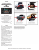
STADARD DUTY POWERED
TAIL LIGHT CONVERTER WITH
SURFACE MOUNT TECHNOLOGY
(SMT)
WITH WIRING KIT
59187
INSTALLATION QUESTIONS? CALL TECHNICAL SUPPORT AT 1-877-287-8634
Figure 1
8B. Using a Trailer: Connect vehicle 4-flat with trailer
wiring and test the converter’s operation using the
trailer lights. Activate the tow vehicle’s left turn, right
turn, tail and stop lights one at a time. If the trailer
lights do not operate properly, disconnect the trailer
4-flat. Using a test light, check for proper operation at
the vehicle 4-flat. If vehicle 4 flat operates properly,
check the trailer for potential problems.