
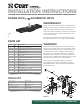
Installation Guide

Step 1
Using a 3/16" drill bit, drill a pilot hole from underneath the
truck bed through the hole in center locator / trim shield (#2).
See figure 2.
Step 1
Place the handle in the unlock position by pulling it out as far
as possible and rotating it clockwise. Note: Never operate
the vehicle with the handle in the unlocked position.
Step 2
Insert the gooseneck ball into the desired position in the
cylinder by aligning the ball's groove with the cylinder pin.
If the groove and pin are not aligned, simply rotate the
gooseneck ball until it drops into place.
Step 3
Place the handle in the lock position by rotating
it counterclockwise until the locking pin snaps
back into position.
INSTALLATION
OPERATION
Toyota Ford
Chevrolet
/ GMC
RAM
Figure 3
Figure 2
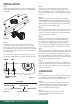
Step 2
Determine the correct safety chain hole locations for the
vehicle; refer to figure 3 below. Using a 5/8" hole saw and
the gooseneck center section (#1) as a guide, drill four holes
from underneath the truck bed for the safety chain loops. Drill
holes should go through the low rib sections. See figure 4 for
correct placement.
To ensure smooth operation of the safety chain loops, use a
3/4" step bit to slightly enlarge the holes from above the truck bed.
Step 3
Using a 4" hole saw, drill the hole from above the truck
bed. Take caution to not drill through the center locator /
trim shield (#2) Note: The use of cutting fluid will ease this
process. Remove the center locator by pulling it up through
the hole.
Step 4
Deburr the cut holes and spray exposed metal with rust
inhibitor. Optional: Insert rubber edging (#9) around the 4"
hole. Place the chrome trim ring (#6) into position and fasten
with three head cap screws (#17). Place two U-bolts (#10)
down through the holes drilled in step 2.
Step 5
From underneath the truck; place a 5/8" washer (#13), spring
(#11), 3/8" washer (#14) and 5/8" nylock nut (#12) on each
of the four U-bolt legs. Tighten the nuts until flush with the
bottom of the U-bolt; see figure 1.
Step 6
Insert the cast lock pin (#7) into the ball cylinder with the
handle hole located on top. Insert the handle (#5) from
the outside of the vehicle through the holes in the center
section; see figure 1. Note: Some models may require
the use of a pliers to bend the metal flange below the bed
outward, allowing the handle to move without interference.
Step 7
Slide one 3/8" washer (#14) and the compression spring (#8)
over the handle before inserting the handle (#5) into the lock
pin (#7). Insert the handle into the locking pin and secure
with a hex head flange screw (#15) and nylock nut (#16); see
figure 1. Note: If needed, add or remove a 3/8" washer (#14)
to ensure proper pull length of locking pin.
Step 8
If removed, reinstall plastic wheel-well covers. Note: Some
models may require trimming of the plastic wheel-well cover.
Trim as needed for reinstallation and access to the handle.
Reinstall the spare tire.
High rib section Hole location
Truck bed
Low rib section
Figure 4
CURTMFG.COM • NEED ASSISTANCE? • 1.800.798.0813 • 60619-INS-RA • PAGE 2