
Owners manual


CAUTION: Remember to allow ample clear-
ance between your trailer and the rear and
cab corner of the truck bumper when making
sharp turns.
2. Locate and mark the area for the center of
the hitch ball.
3. Refer to Curt assembly kits for future install-
ation instruction or select one of the methods
described.
CAUTION: Check installation area for gas lines,
brake lines, etc. before drilling any holes. It may
be necessary to move assembly, but must keep
ball 2"- 6" in front of center of the axle.
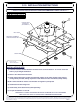
4. The hitch ball must be centered in the truck
bed (Figure 2).
Curt Manufacturing Inc., warrants this product to be free of defects in material and/or workmanship at the time of retail purchase by the original purchaser. If the product is found to be defective,
Curt Manufacturing Inc., may repair or replace the product, at their option, when the product is returned, prepaid, with proof of purchase. Alteration to, misuse of, or improper installation of
this product voids the warranty. Curt Manufacturing Inc.'s liability is limited to repair or replacement of products found to be defective, and specifically excludes liability for incidental or
consequential loss or damage.
C-10 INSTALLATION INSTRUCTIONS
11/26/2007
FLAT PLATE HITCH
DO NOT EXCEED YOUR VEHICLE'S
RATED TOWING CAPACITY!
LOCATION
1. The hitch must be centered between the
sides of the truck bed about 2"- 6" in front
of the rear axle for proper weight distribution
(Figure 1).
FIGURE 1
FIGURE 2
2"- 6"
Forward
of axle
center
PAGE 2
5. To properly transfer towing forces and to avoid
strength, the hitch ball must be supported by
a proper method which ties the hitch ball to
the truck frame. CURT Manufacturing suggests
either of the following two methods:
CHECK ALL PARTS:
(1) C-10 PLATE
(6) 5/8-11 x 2 1/2" Gr.5 Carriage Bolts
(6) 5/8-11 Flange Nuts
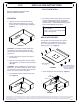
BED PLATE SUPPORT
The installer must make his/her own support
consisting of a hot rolled steel plate, (3/8" x
26" x 40"), angle braces (2" x 2") and frame
brackets (3/8" x 2"). (Figure 3)
ANGLE BRACES
2" x 2" x 3/8"
3/8" x 2" FRAME BRACKETS
Frames may vary, some frame
brackets must be fabricated
for specific applications.
FIGURE 3
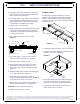
1. Center bed plate in the pickup bed. (Figure 4)
HITCH
ASSEMBLY
BED PLATE
BALL CENTERLINE
FIGURE 4
Axle
Centerline