MODEL 1204/5 MOTOR CONTROLLERS © 2011 CURTIS INSTRUMENTS, INC. 1204 /1205 Manual, p/n 98690 Rev. C: February 2011 CURTIS INSTRUMENTS, INC. 200 Kisco Avenue Mt. Kisco, New York 10549 USA Tel. 914.666.2971 Fax 914.666.2188 www.curtisinstruments.
CONTENTS CONTENTS 1. OVERVIEW ......................................................................1 2. HARDWARE INSTALLATION ......................................3 Controller ...................................................................3 Throttle ......................................................................4 Other Hardware .........................................................6 Main contactor ....................................................7 Forward/reverse contactors ..........
CONTENTS 5. TROUBLESHOOTING AND BENCH TESTING ........25 Operational Notes ......................................................25 In-Vehicle Diagnostic Tests .........................................28 Bench Testing .............................................................32 6. GLOSSARY: FEATURES AND FUNCTIONS ..............35 APPENDIXES A. Functional Description of 1204/1205 Controllers ............A-1 B. Pulse Width Modulation....................................................B-1 C.
FIGURES FIGURES FIG. 1 Curtis 1205 electronic motor controller ..........................1 FIG. 2 Mounting dimensions, Curtis 1204/1205 controller ...........................................3 FIG. 3 Mounting dimensions, Curtis potboxes PB-5, -6, -9, and -10 .............................5 FIG. 4 Curtis footpedal FP-2 .....................................................5 FIG. 5 Typical installation, Curtis 1204/1205 controller ...........................................6 FIG.
FIGURES vi FIG. 16 Alternate PM motor wiring, using 4×SPST contactors to provide freewheeling ....................18 FIG. 17 Preferred PM motor wiring for freewheeling or dynamic braking ...................................18 FIG. 18 Adjustment pots ..............................................................23 FIG. 19 Guide to troubleshooting procedures ..............................27 FIG. 20 Setup for bench testing ...................................................33 FIG.
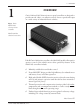
1 — OVERVIEW 1 OVERVIEW Curtis 1204 and 1205 electronic motor speed controllers are designed to provide smooth, silent, cost-effective control of motor speed and torque on a wide variety of industrial electric vehicles. Fig. 1 Curtis Model 1205 electronic motor controller. Model 1204 has identical connections. Like all Curtis 1200 series controllers, the 1204/1205 models offer superior operator control of the vehicle’s motor drive speed.
1 — OVERVIEW ✓ Pot fault circuit shuts off controller if pot wires open ✓ Simple installation with no adjustments required ✓ Tin-plated solid copper bus bars ✓ Push-on connectors for control wiring Familiarity with your Curtis controller will help you to install and operate it properly. We encourage you to read this manual carefully. If you have questions, please contact the Curtis office nearest you. ☞ C AU T I O N Working on electric vehicles is potentially dangerous.
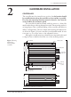
2 — HARDWARE INSTALLATION 2 HARDWARE INSTALLATION CONTROLLER The controller may be oriented in any position, but the location should be carefully chosen to keep the controller as clean and dry as possible. If a clean, dry mounting location cannot be found, a cover must be used to deflect dirt and water splash. The controller should be fastened with four screws to a clean, flat metal surface that provides an adequate heat sink.
2 — HARDWARE INSTALLATION THROTTLE The standard controller throttle input is 0–5kΩ. Curtis potboxes (PB-5, -6, -9, -10) are designed to match this input. Some of these potboxes have a built-in microswitch, eliminating the need to install a separate pedalactuated microswitch. Curtis also offers a self-contained footpedal unit (FP-2) that eliminates the need for fabricating and installing a pedal-potbox linkage.
2 — HARDWARE INSTALLATION Fig. 3 Mounting 45° 42 (1.65) dimensions, Curtis potboxes PB-5, -6, -9, and -10. 10 (0.38) 60 (2.37) 32 (1.25) 6 (0.25) 52 (2.06) 89 (3.5) 102 (4.0) RIGHT-HAND OPERATION LEFT-HAND OPERATION N.C. N.O. COM. COM. N.O. N.C. WITH MICROSWITCH: PB-6 WITHOUT MICROSWITCH: PB-5 WITH MICROSWITCH: PB-9 WITHOUT MICROSWITCH: PB-10 Dimensions in millimeters and (inches) 112 (4.4) 1.8 m (6 ft) 244 (9.6) ≈15 ° GRN (not used) ON BLK 112 (4.4) WHT N.O.
2 — HARDWARE INSTALLATION OTHER HARDWARE The recommended hardware for a typical 1204/1205 controller installation is shown in Figure 5. Contactors should be mounted in a clean, dry location. If such a location is unavailable, a cover should be used to deflect dirt and water splash. The precharge resistor connected to the main contactor, and the coil suppression diodes connected to the main contactor and to the forward/ reverse contactors, are somewhat delicate components.
2 — HARDWARE INSTALLATION Main Contactor Most applications use a main contactor in series with the battery positive (B+) cable to disconnect all power when the system is turned off, as shown in Figure 5. A heavy-duty single-pole, single-throw (SPST) contactor with silver-alloy contacts is recommended, such as an Albright SW80 or SW180 (available from Curtis). A coil suppression diode, such as a Curtis p/n MP-1 (which is rated at 100 volts, 3 amps), should be used on the contactor coil.
2 — HARDWARE INSTALLATION Keyswitch The vehicle should have a master on/off switch to turn the system off when not in use. A keyswitch is typically used for this purpose. Polarity Protection Diode For polarity protection, a diode should be added to the control circuit. This diode must be sized appropriately for the maximum total contactor coil currents.
3 — WIRING 3 WIRING CONNECTIONS: Low Current Three 1/4" push-on terminals are provided for the low current connections to the KSI and throttle inputs. For the control wiring, 0.75 mm2 (#18 AWG) vinyl insulated stranded wire is recommended.
3 — WIRING CONTROL WIRING FUSE POWER WIRING FUSE KEYSWITCH INTERLOCKS PEDAL MICROSWITCH POLARITY PROTECTION DIODE MAIN F R PRECHARGE RESISTOR (250 Ω, 5 W) S1 – POTBOX R REVERSE F A1 FORWARD A2 MAIN + S2 R F BM- B+ A2 Fig. 6 Basic wiring configuration, Curtis 1204/1205 controller. WIRING: SERIES MOTORS Figure 6 is a schematic of the configuration shown in Figure 5.
3 — WIRING turn off the main contactor and the forward/reverse contactors. This will act as a safety feature by removing power from the motor control system when the keyswitch is turned off. Interlocks (seat switches, battery charger interlocks, etc.) should be wired in series so that they turn off the controller KSI and the contactors. Forward/Reverse Wiring (with standard power wiring) These forward/reverse wiring schemes assume the standard power wiring (shown by the heavy lines in Figure 6).
3 — WIRING contacts is added on the forward/reverse switch. Therefore, a double-pole, double-throw (DPDT) center-off switch must be used for this setup. A “hesitation switch” is recommended, to ensure the switch is in neutral long enough to actuate HPD and inhibit plug braking. Plug braking can be reactivated during freewheeling by releasing the throttle and reapplying it.
3 — WIRING Power wiring for mechanical reversing switch (golf car type) As shown in Figure 9, this type of switch mechanically interchanges the two motor field cables by rotating a movable contact bar. The configuration shown is typical; many variations are in use. Fig. 9 Power wiring for reversing with mechanical forward/reverse switch arm. MAIN FUSE + PRECHARGE RESISTOR (250 Ω, 5 W) S1 A2 A1 S2 – BM- Curtis 1204/1205 Manual, Rev.
3 — WIRING Throttle Pot Wiring Standard potbox wiring If the throttle input to the controller is from a Curtis potbox or footpedal, the wiring is simple: just connect the two wires of the potbox/footpedal cable to the two push-on terminals of the controller, as shown in Figure 6. It doesn’t matter which wire goes on which terminal. The wires can be extended as required. Any suitable potentiometer of 5 kΩ nominal resistance will work with the standard throttle input of the 1204/1205 controllers.
3 — WIRING Fig. 12 Bi-directional twist-grip throttle with a standard 20 kΩ pot and a controller with the optional 5kΩ–0 throttle input. nonstandard throttle input. As shown in Figure 12, a standard 20 kΩ pot is used, with its end terminals wired together. The resistance goes from 5 kΩ at neutral to zero at the extremes — the opposite of the standard throttle input configuration. Contact the factory if you need SPEED this type of controller.
3 — WIRING load. You should determine by experiment the proper resistor value to give the desired speed reduction. (NOTE: with reduced speed operation, only top speed is reduced; full power is maintained for starting at low speeds.) Unlike resistor controllers, Curtis 1204/1205 controllers operate efficiently in the reduced speed mode, because little power is lost through the controller. Electronic Throttle Wiring Curtis’s electronic throttle, ET-XXX, is wired as shown in Figure 14.
3 — WIRING WIRING: PM MOTORS Wiring for controllers in vehicles with permanent magnet motors is the same as in those with series motors, except for the forward/reverse circuit. PM motors have only two terminals: the armature brushes. The magnetic field is provided by the permanent magnets and cannot be reversed; instead, the motor is reversed by interchanging the armature leads. The PM motor must be connected, via the forward/reverse circuitry, to the controller’s B+ and M- bus bars.
3 — WIRING violent the effect of the sudden braking will be. If violent braking is not acceptable for your application, use one of the wiring schemes described below to allow the motor to freewheel in neutral or whenever the pedal is released. However, note that sudden braking will still occur if the opposite direction is selected and the pedal is re-applied while the vehicle is still moving.
3 — WIRING If you prefer dynamic braking to freewheeling, you can install a dynamic braking resistor. The motor generates power in slowing down the vehicle; the dynamic braking resistor dissipates this power as heat. The amount of braking torque is determined by the resistance, and is proportional to the vehicle’s speed. The resistor gets hot and must be sized and mounted accordingly.
3 — WIRING INSTALLATION CHECKOUT Carefully complete the following checkout procedure before operating the vehicle. If a step does not test correctly, use the troubleshooting guide (Section 5) to identify the problem. ☞ C AU T I O N Put the vehicle up on blocks to get the drive wheels off the ground before beginning these tests. Don’t let anyone stand in front of or behind the vehicle during the checkout. Make sure the keyswitch is off and the vehicle is in neutral before beginning.
3 — WIRING direction. The motor should not run. Release the throttle and re-apply it—the motor should now run. If the motor runs before you release the throttle, recheck the wiring. G. Take the vehicle down off the blocks and drive it in a clear area. It should have smooth acceleration and good top speed. H. On vehicles that are intended to plug brake, test the plug braking by driving forward at moderate speed and shifting into reverse without letting up on the throttle.
4 — MAINTENANCE & ADJUSTMENT 4 MAINTENANCE & ADJUSTMENT Curtis 1204/1205 controllers and potboxes require only minimal maintenance if properly installed. NOTE: The controllers are sealed and thus are not field serviceable. CONTROLLER Maintenance ☞ C AU T I O N It is recommended that the following two steps be performed occasionally.
4 — MAINTENANCE & ADJUSTMENT Adjustment On some models, the plug braking current and acceleration rate settings are adjustable. On these adjustable controllers, the adjustment pots are located as shown in Figure 18. Fig. 18 Adjustment pots. PLUG CURRENT ADJUST (CW = higher plug current) ACCELERATION RATE ADJUST (CW = faster acceleration) Use the following adjustment procedure. The keyswitch should be off during adjustment. 1.
4 — MAINTENANCE & ADJUSTMENT POTBOX Maintenance Potbox maintenance is similar to controller maintenance: inspect for integrity of connections and mounting, and clean (with a moist rag) as required. Adjustment Curtis potboxes are factory set and rarely require user attention. To test and adjust, connect an ohmmeter to the potbox wires and use this procedure: 1. With the spring holding the lever arm against the return stop, the resistance should be less than 50 ohms. Slowly move the lever.
5 — TROUBLESHOOTING & BENCH TESTING 5 TROUBLESHOOTING AND BENCH TESTING Some behaviors that may seem to suggest controller malfunction do not, in fact, indicate a problem but rather are typical of normal operation. Before undertaking the diagnostic tests, check to see whether your problem is addressed in the first section, “Operational Notes.” The diagnostic tests are designed to enable you to determine whether the trouble is in the controller or in some other part of the motor control circuitry.
5 — TROUBLESHOOTING & BENCH TESTING Hot Controller If the controller gets hot, it does not necessarily indicate a serious problem. Curtis 1204/1205 controllers protect themselves by reducing power to the motor if their internal temperature exceeds 75°C (167°F). Power output will be reduced for as long as the overheat condition remains, and full power will return when the unit cools. In typical applications, overheating will rarely be a problem.
5 — TROUBLESHOOTING & BENCH TESTING Fig. 19 Guide to troubleshooting procedures. [To use this guide, refer to the specified TEST .] PROCEDURES 1 Check for power to the controller Check voltage at CONTROLLER B- and BATTERY B+ terminals. 1-A, B, C if NO It should read full voltage for system. Bad, discharged, or miswired batteries, or corroded connections. 1-C if YES Check voltage at CONTROLLER B- and CONTROLLER B+ terminals. if NO It should read 1 to 5 volts less than full battery voltage.
5 — TROUBLESHOOTING & BENCH TESTING TEST Check for power to the controller 1-A Leave the keyswitch off for these tests. 1-B Verify that battery (-) connects to the B- terminal of the controller. Connect voltmeter (-) lead to this point. 1-C Connect voltmeter (+) to the battery side of the main contactor. Check for full battery voltage. If it is not there, the trouble is in the battery pack, the cables to it, or the power fuse. 1-D Connect the voltmeter (+) lead to the controller B+ terminal.
5 — TROUBLESHOOTING & BENCH TESTING the flow: 1. First, check both sides of the control wiring fuse. 2. Check both sides of the polarity protection diode to make sure its polarity is correct. 3. Check both sides of the keyswitch. 3. Check both sides of the pedal microswitch. 4. Finally, check the contactor coil and controller KSI. If the contactor coil and KSI are getting voltage, make sure the contactor is really working by connecting the voltmeter across its contacts (the big terminals).
5 — TROUBLESHOOTING & BENCH TESTING stop to nearly contacting the pedal-down stop. If the mechanical operation looks okay, replace the potbox. 3-C While you have the potbox wires off the controller, use an ohmmeter to check for shorts between these wires and the vehicle frame. You should see a resistance of at least 1 megohm. If it is lower than that, inspect the wiring for damaged insulation or contact with acid. If necessary, replace the potbox. 3-D Push the wires back on the controller terminals.
5 — TROUBLESHOOTING & BENCH TESTING TEST 4 Check for controller output 4-A The first step is to measure the output drive voltage to the motor at the controller’s M- terminal. 4-B Connect the voltmeter (+) lead to the controller’s B+ terminal. Connect the voltmeter (-) lead to the controller’s M- terminal. 4-C Turn on the keyswitch with the forward/reverse switch in neutral, and then select a direction and watch the voltmeter as you depress the pedal.
5 — TROUBLESHOOTING & BENCH TESTING 2. Use an ohmmeter to check the resistance between the controller’s A2 and B+ terminals. You are testing for the presence of a diode inside the controller, so swap the two leads of the ohmmeter and look for a low resistance one way and a much higher one the other way. If your meter has a diode test function, use it. 3. If you find the diode to be shorted, the controller is defective. 4-H Put the A2 cable back on the controller and reconnect the battery.
5 — TROUBLESHOOTING & BENCH TESTING For controllers with other input options, use whatever kind of potbox is used on the vehicle. 3. a POWER SWITCH to disconnect all power from the test setup. 4. a MAIN CONTACTOR with a 250 ohm, 5 watt resistor across its high-power contacts and a KEYSWITCH to turn it on and off. 5. a TEST LOAD consisting of incandescent light bulbs wired in series to get the same voltage as your power supply. (For example, with a 36 volt battery, use three 12 volt bulbs.) 6.
5 — TROUBLESHOOTING & BENCH TESTING Bench Test Procedure A. Hook up the controller as shown. Connect the voltmeter leads to the controller’s B+ and B- terminals. B. Turn on the power switch (not the keyswitch) and watch the voltmeter. Its reading should build up slowly over several seconds to within a couple of volts of full battery voltage. If this voltage does not come up, the controller is bad. C. Now turn on the keyswitch.
6 — GLOSSARY 6 GLOSSARY: FEATURES and FUNCTIONS Acceleration rate A built-in acceleration rate circuit maintains a maximum rate of power increase to the motor. If the throttle is applied full on at start-up, the acceleration rate setting determines how quickly the controller output increases. The standard setting is such that with the throttle full on, the controller requires approximately one second to reach full output. This feature contributes to smooth, gentle starts.
6 — GLOSSARY the battery. The controller acts like a dc transformer, taking in low current and high voltage (the full battery voltage) and putting out high current and low voltage. The battery needs to supply only a fraction of the current that would be required by a conventional controller (in which the battery current and motor current are always equal). The current multiplication feature gives vehicles using Curtis controllers dramatically greater driving range per battery charge.
6 — GLOSSARY Plug braking The vehicle can be braked electrically by selecting the opposite direction with the forward/reverse switch without releasing the throttle. When the motor is reversed, the armature acts as a generator; the controller regulates the current in the motor field winding to give an appropriate level of plug braking torque. The vehicle brakes smoothly to a stop, then accelerates in the other direction.
6 — GLOSSARY current limit decreases to approximately half its rated value. At the reduced performance level, the vehicle can be maneuvered out of the way and parked. Full current limit and performance return automatically after the controller cools down. Although this action is not damaging to the controller, it does suggest a mismatch. If thermal cutback occurs often in normal vehicle operation, the controller is probably undersized for the application and a higher current model should be used.
APPENDIX A: FUNCTIONAL DESCRIPTION APPENDIX A FUNCTIONAL DESCRIPTION (SHADED AREA REPRESENTS CONTROLLER) POWER SECTION LOGIC SECTION B+ UNDER VOLTAGE DETECT ARM A2 SWITCH KSI PLUG DETECT A2 START-UP TIMER SHUT DOWN THROTTLE INPUT SCALING POT FAULT THROTTLE POT M- + ACCELERATION CIRCUIT ACCELERATION RATE ADJUST LIMIT INTEGRATOR PULSE WIDTH MODULATOR GATE DRIVE CURRENT LIMIT COMPARATORS CURRENT LIMIT DISABLE S2 + MOSFETs OSCILLATOR FILTER CAPACITORS +14 VOLTS TO ALL CIRCUITS HIG
APPENDIX A: FUNCTIONAL DESCRIPTION use with PM motors only, the plug diode and A2 terminal are omitted; however, the Functional Description is written in terms of series motors. LOGIC SECTION B- is the ground return for all of the logic circuitry. For systems over 12 volts, the battery supply is regulated down to 14 volts to power the logic circuitry.
APPENDIX A: FUNCTIONAL DESCRIPTION output and thus hold the current at the limit. Because the voltage across the power MOSFET switch is high when it is off, the current limit comparison is inhibited during the off interval by the current limit disable circuit. The current limit is set as follows: 1. During manufacture, the current limit is set by an internal trimpot (current limit adjust) to the model’s nominal rating. 2.
APPENDIX B: PULSE WIDTH MODULATION APPENDIX B PULSE WIDTH MODULATION (SHADED AREA REPRESENTS CONTROLLER) FREEWHEEL DIODE ARM FILTER CAPS MOTOR + PLUG DIODE FIELD BATTERY + – CURRENT PATH DURING TRANSISTOR ON TIME CURRENT PATH DURING POWER MOSFETS MOTOR CURRENT CONTROL CIRCUITRY THROTTLE POTBOX TRANSISTOR OFF TIME TIME Fig. B-1 Pulse width modulation. A high power semiconductor switch, consisting of an array of parallel power MOSFET transistors, controls the current in the motor windings.
APPENDIX C: WEEE / RoHS APPENDIX C CURTIS WEEE / RoHS STATEMENT, MARCH 2009 WEEE The Directive 2002/96/EC on Waste Electrical and Electronic Equipment (WEEE) was adopted by the European Council and Parliament and the Council of the European Union on January 27, 2003. The aim of the directive was to improve the collection and recycling of WEEE throughout the EU, and to reduce the level of non-recycled waste. The directive was implemented into law by many EU member states during 2005 and 2006.
APPENDIX C: WEEE / RoHS Obligations for buyers of electrical and electronic equipment As of 13 August 2005, in each EU member state where the WEEE directive has been implemented, disposal of EEE waste other than in accordance with the scheme is prohibited. Generally, the schemes require collection and recycling of a broad range of EEE products. Certain Curtis products fall within the scope of the directive and the implemented member state regulations.
APPENDIX D: SPECIFICATIONS APPENDIX D SPECIFICATIONS NOMINAL INPUT VOLTAGE 12V, 24–36V, and 36–48V PWM OPERATING FREQUENCY 15 kHz STANDBY CURRENT less than 20 mA STANDARD THROTTLE INPUT 5 kΩ ±10% (others available) WEIGHT 1204: 1.8 kg (4 lbs) DIMENSIONS 1204: 146mm×170mm×70mm (5.75”×6.75"×2.8”) 1205: 146mm×222mm×70mm (5.75”×8.75"×2.8”) 1205: 2.