SNO-PRO 3000 Assembly and Mounting Instructions - May 2010 Sno-Pro 3000 Series Phase II Polymer Moldboard Plow 7-1/2' Moldboard PN: 1SP751P • 8' Moldboard PN: 1SP81P Sno-Pro 3000 Series Phase II Steel Moldboard Plow 7-1/2' Moldboard PN: 1SP751 • 8' Moldboard PN: 1SP81 8-1/2' Moldboard PN: 1SP851 • 9' Moldboard PN: 1SP91 Curtis Industries Inc. LLC, 111 Higgins St., Worcester, MA 01606 TEL: (800) 343-7676 FAX: (508) 854-3377 For Parts and information visit us at www.Curtisindustries.
Curtis Plows are simple by design. Our unit utilizes an A-Frame assembly for mounting the Electric/Hydraulic unit. This exclusive Curtis feature eliminates the need for Hydraulic Quick-disconnects and also "Hides-Away" our Power unit. Our A-Frame assembly takes the weight of the Power unit off the Lift Frame assembly and allows for increased airflow to the Radiator.
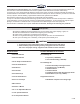
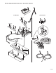
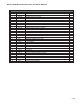
Sno-Pro 3000 Illustrated Parts List - Polyethylene Moldboard & Trip Frame 5 1 2 3 4 12 11 15 10 13 16 14 9 8 7 6 10 Steel Moldboard/Trip Frame Ref # 1 2 3 4 5 6 7 8 9 10 11 12 13 14 15 16 Item # 1TBP21A1 1TBP21B1 1TBP21J1 1TBP21C1 1TBP37 1TBP49A 1TBP49B 1TBP49J 1TBP49C 1TBP50 1TBP133L 1TBP133R Item Description 7-1/2' MOLDBOARD KIT -PHASE II 8' MOLDBOARD KIT - PHASE II 8-1/2' MOLDBOARD KIT -PHASE II 9' MOLDBOARD KIT - PHASE II BLADE MARKER KIT (SET OF 2) 7-1/2' CUTTING EDGE 8' CUTTING EDGE 8-1/2
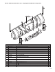
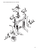
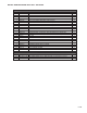
Sno-Pro 3000 Illustrated Parts List - Steel Moldboard & Trip Frame 5 10 1 2 3 4 9 13 11 8 12 6 14 7 8 Polyethylene Moldboard/Trip Frame Ref # 1 2 3 4 5 6 7 8 9 10 11 12 13 14 Item # 1TBP21A-POLY 1TBP21B-POLY 1TBP124-90 1TBP124-96 1TBP37 1TBP49A 1TBP49B 1TBP50 1TBP133L 1TBP133R 1TBP33 1TBP23 1TBP34 1TBP22B1 Item Description 7.5' POLYETHYLENE MOLDBOARD 8.
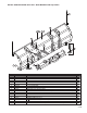
Sno-Pro 3000 Illustrated Parts List - A Frame & Harness 2 3 PLOW SIDE TRUCK SIDE Apply Grease 28 10 14 11 22 4 Apply Grease 10 14 11 24 1 5 15 6 8 12 9 26 25 16 17 13 18 19 Inside A-Frame 29 23 30 20 21 7 27 5 of 29
Sno-Pro 3000 Illustrated Parts List - A Frame & Harness A-Frame/Harness Parts List Ref # 1 2 3 4 5 6 7 8 9 10 11 12 13 14 15 16 17 18 19 20 21 22 23 24 25 26 27 28 29 30 Item # 1TBP29C 8SV-NAFW-B5 Item Description Qty.
Sno-Pro 3000 Illustrated Parts List - Lift Frame 13 8 14 15 19 17 8 16 18 7 12 11 9 22 2 20 4 3 5 G NIN AR W 6 1 12 10 21 7 of 29
Sno-Pro 3000 Illustrated Parts List - Lift Frame Lift Frame Parts List Ref # Item # 1TBP38A 8SV-TBP114-B5 8SV-TBP115-B5 1TBP107 1TBP33B 1TBP103 1TBP112A 1TBP112B Item Description SNO PRO LIFT FRAME ASSEMBLY COMPLETE DRIVER'S SIDE LATCH HOOK PASSENGER'S SIDE LATCH HOOK SNAP LOCK HANDLE (INCLUDED IN 9SV-SLH KIT) SNAP LOCK SPRING (INCLUDED IN 9SV-SLH KIT) PLASTIC HANDLE FOR SNAP LOCK SP3000 (INCLUDED IN 9SV-SLH KIT) LIFT FRAME SIDE PLATE, LH SNO-PRO 3000 (INCLUDED IN 8SV-TBP112-B5 KIT) LIFT FRAME SIDE PLATE,
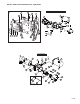
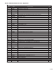
Sno-Pro 3000 Illustrated Parts List - Hydraulics 1 KTI Hydraulics - Aluminum End Head 3 2 5 29 25 7 25 2 39 6 44 43 40 4 12 9 8 41 38 42 10 11 SPX Hydraulics NEW STYLE OLD STYLE 2 1 36 25 31 30 23 35 27 28 14 13 19 2 37 19 3 26 16 17 18 23 16 34 OLDER MODELS ONLY 22 24 33 32 20 21 9 of 29
Sno-Pro 3000 Illustrated Parts List - Hydraulics Hydraulics Parts List Ref # 1 2 3 Item # 1TBP59APC 1TBM8 1TBP59AP1 1TBP59AP2 4 1TBM201 5 1TBM202 6 1TBM203 7 1TBM204 8 1TBP98A 9 1TBP98B 10 1TBP98C 11 1TBP98D 12 1TBP98E SPX Hydraulics Item Description Qty.
Sno-Pro 3000 Assembly Instructions Section 1. Moldboard Assembly A.) Lay Moldboard on its face. Place cardboard under the Moldboard top bend to prevent paint damage. B.) Locate (4) Moldboard Spring Mount Brackets (2 Left, 2 Right). Brackets must be installed with Spring mounting tab pointing to the outside of the Moldboard, not the center. Install each Bracket as shown using (3) 3/8"-16 x 1-1/4" Gr.8 Bolts, Flat Washers and Nylock Nuts. Torque to 30 ft/lbs. Refer to Figure 1 below & Figure 6 on page 14.
Sno-Pro 3000 Assembly Instructions Figure 2. Mount Trip Frame to Moldboard Note direction of Clevis Pins when mounting. 4 3 2 Trip Frame 1 When installing Clevis Pins, work from Left to Right. Tap with a Hammer or Mallet to seat the Clevis Pins. Figure 3.
Sno-Pro 3000 Assembly Instructions Figure 4. Mount Eyebolts to Trip Spring Mounting Brackets Section 3. Mount Trip Springs Thread Jam Nut halfway & add Lock Washer before inserting through Moldboard Bracket A.) Mount (4) Trip Springs (1TBP33) to Trip Frame. See Figure 7 on next page to determine upper or lower mounting hole usage. B.) Thread (1) 5/8" Jam Nut half-way onto each Spring Eyebolt. C.
Sno-Pro 3000 Assembly Instructions Figure 6. Trip Spring Reference View Figure 7.
Sno-Pro 3000 Assembly Instructions Section 4. Mount A-Frame to Trip Frame A.) With Moldboard remaining face down, lift A-Frame assembly over the Trip Frame (with assistance, A-Frame is very heavy) and lower it into the center hole of Trip Frame. Install (1) 1" x 6" Center Bolt (1TBP127) through the Trip Frame and A-Frame. Apply grease to the Center Bolt before inserting, then secure Center Bolt with a 1" Nylon Lock Nut. Do not over tighten, the A-Frame must pivot freely. Figure 8. B.
Sno-Pro 3000 Assembly Instructions Figure 9. Secure Angle Cylinder Rams to Trip Frame 1" x 4" Clevis Pins R L& e ram ins A-F t P ng inser i w S to 3/16" x 2" Cotter Pin Section 5. Lift Frame Side Plate Install (continued) C.) Install Torsion Spring Bushings (1TBP113) through the Torsion Springs and over the Hinge Pins. Fasten loosely with (1) 1/2"-13 x 1" Patch Bolt and 1/2" Flat Washer threaded into each Hinge Pin to secure the assemblies. Do not tighten Bolts at this time.
Sno-Pro 3000 Assembly Instructions Figure 10. Lift Frame Side Plate Installation Torsion Spring and Bushing Right Lift Frame Side Plate Left Lift Frame Side Plate Torsion Spring and Bushing Figure 11.
Sno-Pro 3000 Assembly Instructions Section 6. Mount Lift Frame to A-Frame Side Plates A.) With assistance, position Lift Frame to Side Plates and mount with (4) 5/8"-18 x 1-3/4" Bolts and 5/8"-18 Lock Nuts. To provide proper clearance, 5/8" Bolts must be installed from the inside of Lift Frame with Lock Nuts located on the outside of Lift Frame. This is necessary to provide proper clearance. Tighten 5/8" Gr.8 fasteners mounting the Lift Frame to 225 ft./lbs.
Sno-Pro 3000 Assembly Instructions Figure 13. Lift Frame Mounting Reference View Left Side Shown 5/8" Locknuts installed on Outside of Lift Frame Spring Keeper on Side Plate Torsion Spring Lift Frame Side Plate 1/2" Patch Bolt Torsion Spring Bushing A-Frame Spring Stop Section 7. Lift Frame Setup A.) Mount Lift Arm (1TBP40) to Upper Mounting Tabs of Lift Frame as shown in Figure 14A. Lift Arm mounts with (1) 3/4" x 4-1/2" Clevis Pin (1TBP42) and is secured with a 2" Cotter Pin. B.
Sno-Pro 3000 Assembly Instructions Figure 14. Lift Arm Mounting 3/4" x 4-1/2" Clevis Pin A B Secure with Cotter Pin 1" x 4-1/2" Clevis Pin 3/4" x 2-3/4" Clevis Pin Cotter Pin Insert Clevis Pin through 1" Piston Spacers when mounting Lift Cylinder Point Hose Port toward A-Frame Insert Cylinder End through Lift Frame Tabs and secure with Cotter Pin Figure 15.
Sno-Pro 3000 Assembly Instructions Section 8. Harness Steps A.) If Harness and Lift Cylinder Hose are not pre-wrapped together with Hose Wrapping, tie together using (3) Wire Ties 4" apart starting at the A-Frame exit. B.) Secure the Harness to the Lift Frame using supplied Harness Clips, Bolts, Nuts and Wire Ties. C.) Attach Plow Harness to Lift Frame at Tab 'A' using supplied P-Clamp.
Sno-Pro 3000 Assembly Instructions Figure 17.
Sno-Pro 3000 Assembly Instructions Figure 18. Determine X Height for Correct Side Plate Mounting Holes X Section 9. X Height Procedure A.) Install Mount Kit on vehicle referring to Mount Kit installation procedure. Wire vehicle referring to Page 26 for detailed Harness & Control System installation information. B.) With vehicle parked on level ground and properly ballasted for snow plow use, measure the distance from the ground up to the centerline of the Latch Bar on the Receiver as shown. C.
Sno-Pro 3000 Assembly Instructions Vehicle to Plow Initial Setup Once Vehicle Mount Kit and Harness installations are complete, raise the Plow to the same level as the Mount Kit Receiver. To accomplish this, drive truck close to Plow and attach the Harness Plug. Put 'InCab' Control System into the 'float' position and raise the Plow using the A-Frame Jack Switch to align the rear of the Lift Frame with the Mount Kit Receiver. If necessary, readjust the Side Plate positions.
Sno-Pro 3000 Assembly Instructions Section 10. Plow Light Beam Aiming Procedure A.) Vehicle must be on level surface 25 feet in front of matte-white screen, such as a garage door. The screen should be perpendicular to both the ground and vehicle centerline. B.) Vehicle should be ballasted for snow plowing with a driver. Snowplow Blade should be in place and in the raised position. C.
Sno-Pro 3000 Assembly Instructions Figure 22. Sno-Pro 3000 Harness Layout Ref.: this is for old style harness p/n 1TBP134 (pre-2009 version) Relay for 2009- NOTE: all valve coils have one orange (ground) wire.
Sno-Pro 3000 Assembly Instructions Figure 23.
Sno-Pro 3000 Assembly Instructions Figure 24.
Sno-Pro 3000 Assembly Instructions Section 11. Snow Plow Storage A.) When Plow is disconnected, coat all exposed chrome rods on both Angle Ram Cylinders and Lift Cylinder with Light Grease. The Grease will keep exterior surfaces free from rust and corrosion. B.) Whenever Moldboard is disconnected, coat the exposed chrome rods of both Angle Ram Cylinders with Light Grease to protect them from rust and corrosion. C.) Coat all Pivot Pins and other wear points with Chassis Lubricant. D.