
Datasheet


M O D U L E A S S E M B L Y S P E C I F I C A T I O N S
7 0 0 S E R I E S
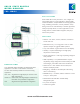
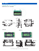
Display 6-digit, 5 or 7 mm high (Models 700, 701, 703)
Dual-Channel 6-digit, 5 mm high (Model 708)
7-digit, 5 mm high Model 720)
Dual-Channel 7-digit, 5 mm high (Model 721)
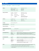
Range & Resolution Hour Meters 99,999.9 hrs. (Models 700, 701, 708)
Maintenance 3,999.9 hrs. (Model 708/2nd Channel)
Counters 999,999 counts (Model 703)
Odometers 999,999.9 increments (Models 720, 721)
9,999,999 (Model 720) optional resolution
Trip 999.9 (Model 721/2nd Channel)
Accuracy Hour Meters ± 0.1% (Models 700, 701, 708)
Counters ± 1 count (Model 703)
Odometers ±1 increment (Model 720, 721)
Humidity 95% Non-condensing at 38°C
Operating Temperature -40°C to + 85°C
Storage Temperature -50°C to + 85°C
Operating Frequency (AC units) 48 to 440 Hz abs.
Memory Main power must be applied for 5 sec to activate memory (with no loss of time/counts).
EEPROM-Data retention 25+ years without power present.
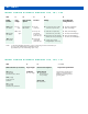
Input Signal (DC Only) Counter Model 703 - 500 Hz max, 50% duty cycle (1ms low, min, between consecutive highs).
Maintenance Monitor Models 701, 708 - Power must be applied for 0.5 sec, min, to accumulate time.
Odometer Model 720 - Varies depending on model configuration (consult factory).
Trip/Odometer Model 721 - 500 Hz max, 50% duty cycle (1ms low, min, between consecutive highs).
Input Signal (AC/DC) Hour Meter Models 701, 708 - Power must be applied for 0.5 sec, min, to accumulate time.
Counter Model 703 - 1 Hz max, 50% duty cycle (500ms low, min, between consecutive highs).
Reset All Models Main power must be applied for a minimum of 0.5 sec. prior to reset signal.
Models 700, 701, 703 6ms, min, at operating voltage.
Model 708 Maintenance 2 or 4 sec, factory programmed; hour meter not resetable.
Model 720 70ms min at operating voltage.
Model 721 Trip channel 2 or 4 sec, factory programmed; odometer is not resetable.
Note: Max Reset frequency is 150Hz for AC models.
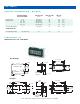
Notes: 1. All modules are supplied with critical components exposed. If the module is being used in an environment other
than specified, the user must take precautions to package the module to provide adequate protection.
2. For proper mechanical support, all module pins should be soldered to the PC-board.
3. To prevent heat damage to components, module face should be 10-20mm minimum away from PC-board
when flow soldered.