
- Acrosser Technology Co., Ltd, Socket 370 Pentium III Grade CPU Card with VGA/LCD/LAN/SCSI Operation Manual

~ Page 7 ~
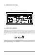
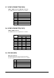
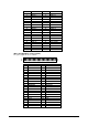
2-2. COMPONENT LOCATIONS
AR-B1682 Connector, Jumper and Component Locations
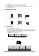
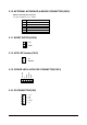
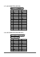
2-3. HOW TO SET JUMPERS
A jumper consists of two or three metal pins with a plastic base mounted on the card, and a small plastic cap
(with a metal contact inside) to connect the pins, so you can set up your hardware configuration by "open" or
close the pins. The jumper can be combined into sets which called jumper blocks. When the jumpers are all
in the block, you have to put them together to set up the hardware configuration. The figure below shows how
it looks.
2 PIN 3 PIN
CAP
JUMPERS AND CAP
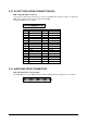
If a jumper has three pins, for example, labelled PIN1, PIN2, and PIN3, you can either connect PIN1 & PIN2 to
create one setting and shorting or connect PIN2 & PIN3 to create another setting. The jumper setting rules are
applied throughout this manual.
BANK2
BANK1
BANK0
Ultra 2 Wide SCSI
CN 1 CN 2
CN 7
CN 5
CN9
CN15
CN13
CN17
CN20
CN4
CN14
CN 8
CO
M2
CN23
KB
CO
M1
J3
CN21
VGA
U21
CN16
CN18
2.
CN11
CN26
CN27
SW2
SW3
J4