740/-41/-42 Manual enAble ® 40 POWERCHAIR CONTROL SYSTEM © 2008 CURTIS INSTRUMENTS, INC. enAble® 40 Manual, p/n 37893 Rev. D: August 2008 CURTIS INSTRUMENTS, INC. 200 Kisco Avenue Mt. Kisco, New York 10549 USA Tel. 914.666.2971 Fax 914.666.2188 www.curtisinstruments.
CONTENTS CONTENTS 1. OVERVIEW ..............................................................................1 Configurations .....................................................................2 Profiles .................................................................................3 MyChair™ ...........................................................................3 Swivel Chair .........................................................................3 Selectable Speed Modes ............................
CONTENTS Compensation Parameters .................................................33 Motors & Brakes Parameters ..............................................34 Battery Parameters .............................................................35 6. MONITOR MENU ................................................................36 7. TUNING GUIDE ...................................................................38 8. DIAGNOSTICS & TROUBLESHOOTING .........................47 9. MAINTENANCE ......................
FIGURES / TABLES FIGURES FIG. 1: Curtis enAble® 40 Powerchair Control System ....................... 1 FIG. 2: Mounting dimensions, 1740 powerbase .................................. 5 FIG. 3: Mounting dimensions, 1741 user handcontrol......................... 6 FIG. 4: Mounting dimensions, 1742 attendant control ........................ 7 FIG. 5: Basic wiring diagram, 1740 powerbase ..................................... 8 FIG. 6: Wiring for the Multi-Function inputs .......................
1 — OVERVIEW 1 OVERVIEW The Curtis enAble® 40 Powerchair Control System provides outstanding versatility packaged in an easy-to-install, easy-to-use set of three components: a powerbase (motor controller) with optional seat actuators and lights, an ergonomic handcontrol with an intuitive icon LCD display, and an optional compact attendant control. The enAble® 40 provides the perfect solution for rear, mid, and front drive powerchairs.
1 — OVERVIEW ✔ Three flexible Multi-Function input pins for advanced seat actuator inhibits, speed limiting, and swivel chair functions usually found only on high-end systems. ✔ Powerbase software is upgradable in the field or in the factory. ✔ Onboard or offboard charging up to 8 amps accommodates high capacity batteries. ✔ Compatible with the 1311 and 1314 programmers. User handcontrol: ✔ Stylish and ergonomic design. ✔ Intuitive at-a-glance icons on LCD display with backlight, viewable in any lighting.
1 — OVERVIEW Profiles Each configuration in the enAble® 40 has two complete operational profiles, each with its own speed, acceleration, and other response parameters. The profiles are used two ways: • MyChair™ — where Profiles 1 and 2 can be blended to provide a range of “feels,” through very simple and safe programming. • Swivel Chair Mode — where Multi-Function Input 3 selects between Profile 1 or Profile 2.
1 — OVERVIEW Multi-Function Inputs The enAble® 40 introduces a level of seat and vehicle speed limiting/inhibit modes normally found on only the highest end Rehab systems. Three MultiFunction Inputs on the powerbase plus the Inhibit on the handcontrol charger port allow for flexible charger configurations (onboard/offboard), seat actuator halts in one or both directions, and up to four separate speed limits linked to these inputs.
2 — INSTALLATION & WIRING 2 INSTALLATION AND WIRING INSTALLING THE ENABLE® 40 SYSTEM The enAble® 40 modules—powerbase, user handcontrol, and attendant control—have been designed for convenient installation. Mounting the 1740 Powerbase The powerbase is easily mounted to the chair by means of two bolts, and can be oriented in any position. Fig. 2 Mounting dimensions, Curtis 1740 powerbase.
2 — INSTALLATION & WIRING Mounting the 1741 Handcontrol Brass inserts in the user handcontrol allow it to be securely mounted and removed/reinstalled many times. The handcontrol is designed to fit both tube and plate mounting systems. Fig. 3 Mounting dimensions, Curtis 1741 user handcontrol. Dimensions in millimeters (and inches) Curtis enAble® 40 Manual, Rev.
2 — INSTALLATION & WIRING Mounting the 1742 Attendant Control Like the handcontrol, the attendant control has brass inserts that allow it to be securely mounted and removed/reinstalled many times. The field replaceable cable can be rotated to either of two positions, fore and aft. Fig. 4 Mounting dimensions, Curtis 1742 attendant control. Dimensions in millimeters (and inches) Curtis enAble® 40 Manual, Rev.
2 — INSTALLATION & WIRING POWERBASE WIRING Wiring for the 1740 powerbase is shown in Figure 5. The connections to the 14-pin connector are optional, depending on the level of functionality desired. For use with the simplest handcontrol (the basic drive-only version), no logic connections are required; for use with the full featured handcontrol (drive with lights and seat actuators), all the connections shown in Figure 5 are required.
2 — INSTALLATION & WIRING Fig. 6 Wiring for the Multi-Function inputs. Molex High Current Contacts must be used for onboard charging through this connector. Allowable current is 8 amps continuous. Curtis enAble® 40 Manual, Rev.
2 — INSTALLATION & WIRING CONNECTING THE CONTROL MODULES The communications cable on the 1741 user handcontrol and on the 1742 attendant control each terminate in a plug that fits into the powerbase’s 6-pin connector. The attendant control’s cable includes a Y-junction into which the user handcontrol’s cable connects, as shown in Figure 7. Fig. 7 Connecting the control modules to the powerbase.
3 — USER HANDCONTROL 3 USER HANDCONTROL (1741) The enAble® 40 handcontrol is designed to be user-friendly. The keypad buttons are responsive and clearly marked. The LCD display is crisp and clear, with intuitive icons and backlighting to enhance daytime and nighttime readability. The communication cable is thin, flexible, and field replaceable. The handcontrol is the main user interface to the control system. All user commands come from the handcontrol’s keypad and joystick.
3 — USER HANDCONTROL Drive Only (4-button keypad) The Drive Only keypad has four buttons: On/Off, Horn, Speed Up, and Speed Down. These four basic buttons are standard on all the keypad versions. Fig. 8a Keypad for basic Drive Only handcontrol; these buttons are standard on all the keypads. On/Off Button The Power On/Off button is located at the top of the keypad, above the display. This button can also be used to lock the chair; see Handcontrol menu, page 24.
3 — USER HANDCONTROL Drive with Lights (8-button keypad) This keypad’s eight buttons are the standard four (On/Off, Horn, Speed Up, Speed Down) plus a Running Lights button, two buttons for the turn indicators (left and right), and a Hazard Lights button. Fig. 8b Keypad for the Drive + Lights handcontrol. Running Lights Button Pressing the Running Lights button turns on the headlamps and any other running lights on the chair. Pressing the button again turns them off.
3 — USER HANDCONTROL Drive with Actuators (6-button keypad) This keypad’s six buttons are the standard four (On/Off, Horn, Speed Up, Speed Down) plus two buttons to activate the two actuator modes. The mode buttons show one dot (for Mode 1) and two dots (for Mode 2). Fig. 8c Keypad for the Drive + Actuators handcontrol. Actuator Mode Buttons With this handcontrol, there’s a button for each mode: Actuator Mode 1 and Actuator Mode 2. The joystick must be in neutral before pressing an actuator mode button.
3 — USER HANDCONTROL Drive with Actuators and Lights (8-button Keypad) This keypad’s eight buttons are the standard four (On/Off, Horn, Speed Up, Speed Down) plus a Running Lights button, two buttons for the turn indicators (left and right), and an Actuator Mode button. The hazard lights (i.e., flashing left and right turn signals, front and rear) are activated by pressing both turn indicator buttons simultaneously. They will continue to flash even if the system is powered down.
3 — USER HANDCONTROL LCD DISPLAY The LCD on the handcontrol briefly displays all of the system’s icons, as shown in Figure 9, during its self-test routine on startup. Seat Actuator Battery Discharge Indicator (BDI) Key Lock Running Lights Joystick Seatback Actuator Brake Fault Warning ! L Turn Indicator Lights Legrest Actuators Charging Plug Temperature Warning Powerbase Drive Motor Attendant Control Speed Mode R Turn Indicator Lights Fig. 9 LCD display on the handcontrol.
4 — ATTENDANT CONTROL 4 ATTENDANT CONTROL (1742) The attendant control is a compact joystick module that allows an attendant to control the drive and seat functions while walking behind at a comfortable pace. It has direct seat control access and easy-to-read BDI, Mode, and Actuator indicator LEDs. Fig. 10 Attendant control Actuator LEDs module.
4 — ATTENDANT CONTROL Pressing the Mode button longer than one second while the joystick is in neutral will select the Seat mode. The Mode LED will go dark, and the LED corresponding to the active actuator(s) will be illuminated in the chair icon. Moving the joystick to the right cycles through all programmed Actuator modes. See Seat menu, page 28. When the attendant control is used to select seat modes, the corresponding chair icon component on the handcontrol’s LCD display also lights up.
5 — PROGRAMMABLE PARAMETERS 5 PROGRAMMABLE PARAMETERS The enAble® 40 Powerchair Control System has a number of parameters that can be programmed using a Curtis 1311 handheld programmer or Curtis 1314 PC Programming Station. The programmable parameters allow the vehicle’s performance to be customized to fit the needs of specific applications. For information on programmer operation, see Appendix B. For information on how to use the parameters to optimize chair performance, see Section 7: Tuning Guide.
5 — PROGRAMMABLE PARAMETERS: Configuration and MyChair Parameters The 1740 powerbase holds four complete data sets containing values for all the programmable parameters. This allows the OEM to have one controller whose four configurations are set up to match four different chair models. The Configuration parameter is used to select which of these four configurations is active.
5 — PROGRAMMABLE PARAMETERS: Drive Parameters (for Profiles 1&2) The Drive menu contains the major parameters that affect the forward and reverse speed, response, and feel of the chair. There are separate Drive menus for Profile 1 and Profile 2. DRIVE MENU PARAMETER RANGE DESCRIPTION Fwd Max Speed 1–100 % Full forward speed when speed limit is 100%. Fwd Min Speed 1–100 % Full forward speed when speed limit is 0%. Fwd Accel High Speed 1–100 % Forward acceleration when speed limit is 100%.
5 — PROGRAMMABLE PARAMETERS: Steer Parameters (for Profiles 1&2) The Steer menu contains the major parameters that affect the steering and turning response, speed, and feel of the chair. There are separate Steer menus for Profile 1 and Profile 2. STEER MENU PARAMETER RANGE DESCRIPTION Turn Max Speed 1–100 % Turn speed when speed limit is 100%. Turn Min Speed 1–100 % Turn speed when speed limit is 0%.
5 — PROGRAMMABLE PARAMETERS: Steer Parameters (for Profiles 1&2) Fig. 11 Electronic gating, using the Gate Shape parameter. Fig. 12 Dynamic turn radius control, using the patent-pending Speed Full Turn and Speed No Turn parameters. Curtis enAble® 40 Manual, Rev.
5 — PROGRAMMABLE PARAMETERS: Handcontrol Parameters The three parameters in the Handcontrols menu apply to the 1741 user handcontrol and the 1742 attendant control. Following this menu are four additional submenus related to these controls: Speed Mode, Joystick, Sound & Display, and Handcontrol Inhibit. HANDCONTROLS MENU PARAMETER Auto Shutoff RANGE 0–60 min DESCRIPTION The chair will automatically shut down after this period of inactivity.
5 — PROGRAMMABLE PARAMETERS: Speed Mode Parameters ☞ The Speed Mode menu allows the therapist, dealer, or OEM to set the number of modes that can be selected by the user and by the attendant, and the speed limit of each mode. It is important to note that the speed limit setting works like a speed pot.
5 — PROGRAMMABLE PARAMETERS: Joystick Parameters JOYSTICK MENU PARAMETER RANGE Perimeter Deadband 0–50 % Sets how close to the stop (gate) the joystick must be moved before it is considered full on. With a setting 0%, the joystick must move all the way to the stop. Center Deadband 5–20 % Sets how far from center the joystick must move to begin chair movement and release the brakes. With the minimum setting of 5%, only a small movement is required to start the chair moving.
5 — PROGRAMMABLE PARAMETERS: Sound & Display and Charger Inhibit Parameters SOUND & DISPLAY MENU PARAMETER RANGE DESCRIPTION Rev Beep On/Off Provides a backup alarm when the chair is in reverse. Command Beep On/Off Provides a short beep each time a button is pressed. Error Beep On/Off Provides a beep when errors are present. Backlight Day 0–100 % Sets the brightness of the LCD display backlight when the running lights are off.
5 — PROGRAMMABLE PARAMETERS: Seat Parameters The parameters in the Seat menu select which part of the seat each actuator controls, how fast it can move, and how end-stops are detected. Additional parameters enable the simultaneous use of two actuators and select how the joystick will drive the seat functions. SEAT MENU PARAMETER RANGE Toggle Control Mode On/Off Setting this parameter On allows the joystick to be used as a toggle switch.
5 — PROGRAMMABLE PARAMETERS: Lights and Current Limits Parameters LIGHTS MENU PARAMETER Running Lights RANGE DESCRIPTION On/Off Set to On if the vehicle has running rights. Running Light Volts 12–24 V Defines the voltage for the running lights. Bulbs will be held at a constant brightness. Min Light Current * 0–26.5 A Defines the minimum allowed driver current for the running lights; below this current, a fault will be declared. Indicators On/Off Set to On if the vehicle has indicator lights.
5 — PROGRAMMABLE PARAMETERS: Multi-Function Input 1 Parameters The powerbase has three Multi-Function Inputs, which can be used to create a very flexible array of seat adjustment and drive speed limiting functions. The speed limits imposed by the Multi-Function inputs act like speed modes; they cause an interpolation between each of the min and max parameter pairs in the active profile (Profile 1 or 2). Note that the final speed limit of the chair is always the lowest of all the applicable limits.
5 — PROGRAMMABLE PARAMETERS: Multi-Function Input 2 Parameters Multi-Function Input 2 menu can be used to inhibit one or both actuators, and to set a corresponding speed limit. Multi-Function Input 2 is at Pin 6 on the 14-pin connector; see Figure 6, page 9. MULTI-FUNCTION INPUT 2 MENU PARAMETER RANGE Off / Seat DESCRIPTION 0–1 0 = Multi-Function Input 2 ignored. 1 = Inhibit and/or Speed Limit functions active, depending on whether input is high or low (see next parameter).
5 — PROGRAMMABLE PARAMETERS: Multi-Function Input 3 Parameters Multi-Function Input 3 can be used to provide a swivel chair function (=1). Alternatively, it can be used to provide an appropriate speed limit when a switch is activated (=2). Multi-Function Input 3 is at Pin 7 on the 14-pin connector; see Figure 6, page 9. MULTI-FUNCTION INPUT 3 MENU PARAMETER Off / Swvl / Seat RANGE DESCRIPTION 0–2 0 = Multi-Function Input 3 ignored. 1 = Provides swivel chair function.
5 — PROGRAMMABLE PARAMETERS: Compensation Parameters COMPENSATION MENU PARAMETER RANGE DESCRIPTION High Speed Comp 0–100 % Sets motor load compensation at high speeds. Higher values provide stronger disturbance rejection, while smaller values provide smoother operation. Low Speed Comp 0–100 % Sets motor load compensation at low speeds. Higher values provide stronger disturbance rejection, while smaller values provide smoother operation.
5 — PROGRAMMABLE PARAMETERS: Motors & Brakes Parameters MOTORS & BRAKES MENU PARAMETER RANGE Auto-Trim On/Off Motor Trim -127 – +127 DESCRIPTION Enables/disables the patented Auto-Trim feature; see page 4. Sets the motor trim, allowing for straight line tracking despite differences in motor characteristics. Setting this parameter to zero provides no steering correction. Open Motor Detect On/Off Enables the controller’s algorithm for determining whether a drive motor is not connected.
5 — PROGRAMMABLE PARAMETERS: Battery Parameters MOTORS & BRAKES MENU, cont’d PARAMETER RANGE DESCRIPTION Brake Turn-On Voltage 12–24 V Sets the initial voltage of the brakes when they first turn on. Set this parameter to match your brakes. Brake Cutback Voltage 6–24 V Sets the level to which the brake coil voltage will be reduced after approx. 1 sec at full battery voltage. This feature saves power and prevents overheating. Brake Delay 0–1.
6 — MONITOR MENU 6 MONITOR MENU Through its Monitor menu, the programmer provides access to real-time data during chair operation. The Monitor menu has six submenus, which follow the Active Config parameter at the top of the menu: MONITOR MENU —Active Config —Handcontrol —Seat —Lights —Motor Controller —Motors & Brakes —Battery MONITOR MENU DISPLAY RANGE ITEM Active Config 1–4 DESCRIPTION Configuration that is currently selected.
6 — MONITOR MENU MONITOR MENU, cont’d ITEM DISPLAY RANGE DESCRIPTION LIGHTS • • • Indicator Current 0–26.5 A Current through the indicator lights. Running Light Current 0–26.5 A Current through the running lights. M OTO R C O NTROLLER • • • M1 Bridge Temp 0 – 200 °C Temperature of power section for drive motor 1. M2 Bridge Temp 0 – 200 °C Temperature of power section for drive motor 2.
7 — TUNING GUIDE 7 TUNING GUIDE This section shows you how to to zero in on the desired drive feel for the chair. The procedures should be conducted in the sequence given, because successive steps build upon the ones before. Please follow them carefully and do not skip over any steps. Make sure you are in a clear and open area when you start the tuning process. You will need to use a programmer in order to conduct these procedures.
7 — TUNING GUIDE 3 Set up the Speed Modes The chair can have up to nine different speed modes. The operator selects them by pressing the handcontrol’s Up and Down buttons. 1. Define how many speed modes there will be, using the Number of Modes parameter (Program > Handcontrol > Speed menu). STEP 2. Define the maximum limit for each of these speed modes, starting with Speed 1. Set the highest speed mode you have to 100%. The speeds between Speed 1 and this highest speed do not need to be linear.
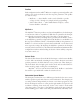
7 — TUNING GUIDE ☞ STEP 7. Return to the Motor Test parameter and turn it Off. STEP 8. To set the controller to automatically compensate for motor resistance changes due to motor temperature, turn the Motor R Measure parameter On. Set the Motor Test Current parameter to 25%. Drive the chair. If the ride is more jumpy than before, increase the Motor Test Current until the chair drives normally. The controller will now accurately detect a hot motor and compensate for changes in motor resistance.
7 — TUNING GUIDE 8 Set Up Compensation Setting the compensation parameters carefully will provide the proper control force during turning, caster reversal, and hill and curb climbing, and will also provide smooth and responsive acceleration and steering. Once the compensation values have been set, typically they do not need to be adjusted again. However, sometimes the chair feels too jumpy or too sluggish even after the best attempts to tune the drive and steering parameters.
7 — TUNING GUIDE STEP 9. Next we will adjust the Fwd Decel, which uses an advanced algorithm. First, set the Soft Stop parameter to 10%. a. Select a speed mode that commands about 10–20% speed. Set Fwd Decel High Speed, Mid Speed, and Low Speed to the same value, and adjust all three parameters alike until deceleration feels right from this low speed. b. Select a speed mode that commands about 50% speed.
7 — TUNING GUIDE bl Set Up the Turn Accel/Decel Rates Adjusting the feel of the steering is one of the most critical steps in the tuning process. The turn speeds, accelerations, and decelerations must all match with the chair drive wheel configuration, travel speeds, and joystick mapping to provide safe, responsive, and intuitive control. One of the most important points is to always keep the Turn Decel parameters higher (faster) than the Turn Accel parameters.
7 — TUNING GUIDE to increase or decrease the speed the chair drives while making a wide turn. c. To add Dynamic Turn Radius Control, first adjust the Speed Full Turn parameter. Select the slowest speed mode and drive the chair at full throttle, making fast sharp turns left and right. If the chair responds as desired, select the next higher speed mode and again drive the chair at full throttle, making fast sharp turns.
7 — TUNING GUIDE STEP 1. Drive the chair full speed and note how well it responds to small movements. Adjust the Steering Sensitivity value for more response. STEP 2. If the chair is still not responsive, you may need to raise the High Speed Comp value set during procedure 8. Conversely, if it is too jittery or nervous, even at low settings, you may need to lower the High Speed Comp value.
7 — TUNING GUIDE set higher than the Low Speed Comp parameter, and can be set higher than 100%. Be careful, though, as too high settings can cause the chair to jerk and oscillate. If this happens, lower the Anti-Rollback Comp value. 46 STEP 4. Adjust the Extra Uphill Comp parameter next. This adds a voltage to hold the chair still, and stops nearly all rollback. Starting from a setting of 0V, drive up the hill and release the joystick.
8 — DIAGNOSTICS & TROUBLESHOOTING 8 DIAGNOSTICS AND TROUBLESHOOTING The enAble® 40 control system detects a wide variety of faults or error conditions, and communicates information about them in three ways: • By the icons displayed in the LCD on the user handcontrol • By flashing LEDs on the attendant control • By displaying the fault name in the programmer’s Faults menu. The alerts indicated on the handcontrol LCD give the user a pretty good indication of what the problem is (see Table 1).
8 — DIAGNOSTICS & TROUBLESHOOTING HANDCONTROL DIAGNOSTICS Faults are typically indicated by the wrench icon plus a flashing icon for the problem site. Warnings are indicated by the warning symbol instead of the wrench—or, in the case of keylock, by the key icon, and in the case of over/ undertemperature, by the thermometer icon. Although additional icons may be displayed at the same time, the ones shown in Table 1 are the ones that define the various fault warnings.
8 — DIAGNOSTICS & TROUBLESHOOTING Table 1: HANDCONTROL INDICATORS, cont’d HANDCONTROL LCD DISPLAY ! ! FAULT/WARNING REMEDY Undervoltage Warning 1. 2. 3. 4. Overvoltage Warning. 1. Wait for voltage to come down. 2. Replace old battery. 3. Check charger; replace if faulty. Controller Over/Undertemperature Warning. 1. If too hot, wait for controller to cool. 2. If too cold, drive chair in limited current mode until controller warms up. Drive Thermal Warning. 1. Wait for motor to cool.
8 — DIAGNOSTICS & TROUBLESHOOTING Table 1: HANDCONTROL INDICATORS, cont’d HANDCONTROL LCD DISPLAY + FAULT/WARNING REMEDY Low battery. 1. Recharge battery. Locked mode. * 1. Unlock the system. Chair under attendant control. * 1. Turn off attendant control (1742). Battery charging; inhibit. * 1. Unplug charger when charging is complete. The bars on the battery icon light up in a chase sequence. * These icons indicate a problem only if they appear when they shouldn’t.
8 — DIAGNOSTICS & TROUBLESHOOTING ATTENDANT CONTROL DIAGNOSTICS The LEDs on the attendant control are used to communicate information about faults, warnings, and battery charging. The Mode LED, the BDI LED, and the LEDs in the chair icon signal warnings by flashing. For more information, turn on the user handcontrol and refer to Table 1. Table 2: ATTENDANT CONTROL FAULT & WARNING INDICATORS SIGNAL FAULT/WARNING/INFO COMMENTS MODE LED (RED) ✲ (Various faults and warnings.
9 — MAINTENANCE 9 MAINTENANCE There are no user serviceable parts in the Curtis 1740 controller. No attempt should be made to open, repair, or otherwise modify the controller. Doing so may damage the controller and will void the warranty. Replacement parts are, however, available for the Curtis 1741 user handcontrol and Curtis 1742 attendant control. See Appendix C for part numbers.
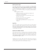
APPENDIX A: BDI SETUP APPENDIX A BATTERY DISCHARGE INDICATOR (BDI) SETUP The Battery Discharge Indicator on the enAble® 40 system is quite flexible and, once set up, will provide the user with reliable information on the status of the battery system. The batteries can be charged either with an onboard charger or an offboard charger. With onboard charging, the charger is permanently mounted on the chair, and one of the Multi-Function Inputs is used for charging functions.
APPENDIX A: BDI SETUP Step 3. Setting the Empty Voltage 3.a Normally a value of 1.7 volts per cell is used as the empty point. This corresponds to a setting of 20.4 V. For some sealed batteries, this may be too low. Consult the battery manufacturer if you are unsure. Step 4. Setting the Discharge Factor 4.a Resume driving the chair in a normal cycle. 4.b Pay attention to the battery voltage, BDI, and time. 4.
APPENDIX A: BDI SETUP If you want to use the partial charge feature: 5.c Based on the Amp Hour rating of the batteries and the charger’s average amp output, initially calculate and set the Charge Factor using this formula: Charge Factor = 10 * (Battery amp-hrs / Charger amps). 5.d Starting with the dead battery from Step 4, plug in the charger. After 10 minutes of charging, measure the battery voltage with a meter. Set the Start Charge Voltage parameter to this value. 5.
APPENDIX B: PROGRAMMER OPERATION APPENDIX B PROGRAMMER OPERATION Curtis programmers provide programming, diagnostic, and test capabilities for the enAble® 40 Powerchair Control System. The programmer plugs into the 5-pin connector on the user handcontrol; power is supplied by the powerbase. Two programmers are available: the PC Programming Station (1314) and the handheld programmer (1311).
APPENDIX B: PROGRAMMER OPERATION HANDHELD PROGRAMMER (1311) The 1311 programmer is easy to use, with self-explanatory functions. After plugging in the programmer, wait a few seconds for it to boot up and gather information from the controller. For experimenting with settings, the programmer can be left plugged in while the vehicle is driven. The bookmark keys can make parameter adjustment more convenient. To set a bookmark, press one of the three bookmark keys for more than two seconds.
APPENDIX C: CONNECTORS & PARTS LIST APPENDIX C MATING CONNECTORS & REPLACEMENT PARTS High Power Connectors, 1740 Powerbase Complete battery and motor connector kit Curtis p/n 381570001 The kit contains: 2 Motor connector housings Curtis p/n 37383 1 Battery connector housing Curtis p/n 37384 6 Female Maxi Power Timer contacts Curtis p/n 12690FC34 4 Female Std Power Timer contacts Curtis p/n 12690FC35 2 Motor connector boots Curtis p/n 37938 1 Battery connector boot Curtis p/n 37939 Items in t
APPENDIX D: SPECIFICATIONS APPENDIX D SPECIFICATIONS Table D-1: 1740 POWERBASE Nominal input voltage PWM operating frequency 24 V 15.