CAP-215 APRIL, 2003 REV. D OIL-LESS COMPRESSOR OPERATION AND INSTRUCTION MANUAL OIL-LESS COMPRESSOR MODELS OL 512 SINGLE STAGE 3 H.P. OL 512 SINGLE STAGE 5 H.P. OL 524 TWO STAGE 5 H.P. OL 812 SINGLE STAGE 7 1/2 H.P. OL 812 SINGLE STAGE 10 H.P. CAUTION Before installing this compressor, read and understand the safety precautions contained within this manual CURTIS - TOLEDO, INC. 1905 Kienlen Avenue, St.
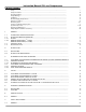
Instruction Manual Oil-Less Compressors TABLE OF CONTENTS Safety................................................................................................................................................... Safety Precautions............................................................................................................................... Receiving Delivery...............................................................................................................................
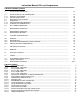
Instruction Manual Oil-Less Compressors TABLE OF CONTENTS (CONT’D) 8. INSTALLATION OPERATION................................................................................................................. 23 8.1. 8.1.1. 8.1.2. 8.2. 8.3. 8.3.1. 8.3.2. 8.4. INSTALLATION OF THE COMPRESSOR............................................................................................... NATURAL VENTILATION..........................................................................................................
Instruction Manual Oil-Less Compressors Fig. 19 Fig. 20 Fig. 21 Fig. 22 Fig. 23 2 STAGE COMPRESSOR DIMENSIONS (070308-1015)........................................................................... 1 STAGE COMPRESSOR DIMENSIONS (070307-1015)........................................................................... 1 STAGE COMPRESSOR DIMENSIONS (077734).................................................................................... D51.
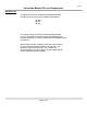
CAP-215 Instruction Manual Oil-Less Compressors INTRODUCTION THIS MANUAL CONTAINS OPERATION AND MAINTENANCE SCHEDULES FOR THE OIL-LESS COMPRESSOR MODELS: OL 512 OL 524 OL 812 ALL INSTRUCTIONS SHOULD BE OBSERVED AND CARRIED OUT IN THE ORDER LAID DOWN TO PREVENT DAMAGE AND PREMATURE WEAR TO THE EQUIPMENT AND THE COMPRESSORS SERVED BY IT.
CAP-215 Instruction Manual Oil-Less Compressors SAFETY At Curtis-Toledo, Inc. safety is a primary concern. Beginning with the design stage, safety is built into every "Curtis Compressor". It is the purpose of this manual to pass along the "safety first" concept to you by providing safety precautions throughout its pages. “WARNING!”, "CAUTION!", and "DANGER!" are displayed in large bold capital letters to call attention to areas of vital concern.
CAP-215 Instruction Manual Oil-Less Compressors DANGER! • Do not install a shutoff valve in the compressor discharge line without first Installing a pressure relief valve of proper size and design between the shutoff valve and the compressor. • Do not use plastic pipe, rubber hose, or lead-tin soldered joints In any part of the compressed air system. • Alterations must not be made to this compressor without Curtis-Toledo's approval.
CAP-215 Instruction Manual Oil-Less Compressors RECEIVING DELIVERY Immediately upon receipt of compressor equipment and prior to completely uncrating, the following steps should be taken: 3. Read the compressor nameplate to verify the model and size ordered. 1. Inspect compressor equipment for damage that may have occurred during shipment. If any damage is found, demand an inspection from the carrier. Ask the carrier how to file a claim for shipping damages. (Refer to FREIGHT DAMAGE for complete details.
CAP-215 Instruction Manual Oil-Less Compressors ELECTRICAL SUPPLY REQUIREMENTS The electrical installation of this unit should be performed by a qualified electrician with knowledge of the National Electrical Code (N.E.C.), O.S.H.A. code and/or any local or state codes having precedence. result in physical harm and/or property damage. Do not bypass motor overcurrent protection. Before installation, the electrical supply should be checked for adequate wire size and transformer capacity.
CAP-215 Instruction Manual Oil-Less Compressors All inlet piping should be at least the same size (or larger) in diameter as the inlet connection to the compressor. For every 10 feet of inlet piping or every 900 bend, increase the inlet piping diameter by one pipe size. The inlet piping must be thoroughly clean inside. Remove all weld slag, rust or dirt. Galvanized pipe with threaded or flanged fittings is preferred.
CAP-215 Instruction Manual Oil-Less Compressors SYSTEM COMPONENTS installed between the manual shutoff valve and the compressor. Efficiency and safety are the primary concerns when selecting components for compressed air systems. Products of inferior quality can not only hinder performance of the unit, but could cause system failures that result in bodily harm or even death. Select only top quality components for your system.
CAP-215 Instruction Manual Oil-Less Compressors SYSTEM COMPONENTS (CONTINUED) WARNING! WARNING! Never exceed the designed pressure for the system or overload the motor beyond its Maximum Amp Draw. • • Never assume a compressor is safe to work on just because it is not operating. It may be in the automatic stand-by mode and may restart any time. Follow all safety precautions outlined in STOPPING FOR MAINTENANCE. Full Load Amps x Service Factor = Max-imum Amp Draw.
CAP-215 Instruction Manual Oil-Less Compressors PULLEY ALIGNMENT & BELT TENSION Setting Belt Tension Improper pulley alignment and belt tension are causes for motor overloading, excessive vibration and premature belt and/or bearing failure. To prevent this from happening, check the pulley alignment and belt tension on a regular basis. 2. Determine the amount of deflection (in inches) required to measure deflection force (in pounds) by multiplying the span length x 1/64 (i.e.
CAP-215 Instruction Manual Oil-Less Compressors 1. GENERAL 1.1. PURPOSE AND SHORT DESCRIPTION The 1-stage oil-less compressor model OL 512, and OL 812, as well as the 2-stage oil-less compressor model OL 524, are used to compress air in the pressure ranges up to 110 psi (1-stage compressor models) to 220 psi (2-stage compressor models) All compressors operate with three cylinders and are air-cooled (Fig. 1 to Fig. 4). The cylinders are set in Yconfiguration, allowing for a small compact design.
CAP-215 Instruction Manual Oil-Less Compressors Fig.
CAP-215 Instruction Manual Oil-Less Compressors Fig.
CAP-215 Instruction Manual Oil-Less Compressors Fig.
CAP-215 Instruction Manual Oil-Less Compressors Fig.
CAP-215 Instruction Manual Oil-Less Compressors Fig.
CAP-215 Instruction Manual Oil-Less Compressors Fig.
CAP-215 Instruction Manual Oil-Less Compressors 1.2. DESIGN AND MODE OF OPERATION 1.2.1 DESIGN The design of the oil-less compressor is shown in Fig. 1 to Fig. 4. For drawings refer to the annex of this manual. Fig. 7: Position of stages at 2-stage compressor 1.2.2. Mode of Operation 1-stage compressor The positions stated refer to Fig. 1.
CAP-215 Instruction Manual Oil-Less Compressors 2-stage compressor The position stated refer to Fig. 3. The two first stages (5) of the oil-less compressor draw in the outside air via the intake filter (14) and the crankcase and compressed to an intermediate pressure of approx. 60 to 70 psi. The compressed air is cooled back to the original temperature in the intermediate coolers (3) and is then lead to a manifold (10).
CAP-215 Instruction Manual Oil-Less Compressors 1.3. TECHNICAL DATA 1 -stage compressor OL 512 No. of stages Intake volume b) Intake pressure Delivery Operating pressure, max. No. of cylinders Cylinder bore Piston stroke Speed Weight Drive input c) Compressor rotation Min./max. ambient temperature 1 31.8 cfm atmospherical 17 cfm at 110 psi 110 psi 3 3.3 inches 2 inches 960 min.-1 (rpm) 121 lbs. 5.51 H.P. counterclockwise facing flywheel +40...+105Fº 2-stage compressor OL 524 No.
CAP-215 Instruction Manual Oil-Less Compressors Technical Data 1 -stage compressor OL 812 No. of stages Intake volume f) Intake pressure Delivery Operating pressure, max. No. of cylinders Cylinder bore Piston stroke Speed Weight Drive input g) Compressor rotation 1 48 cfm atmospherical 31.6 cfm at 110 psi 110 psi 3 3.3 inches 3.1 inches 1,000 min.-1 (rpm) 132 lbs. 10 H.P. counterclockwise facing flywheel +40...+105Fº Min./max.
CAP-215 Instruction Manual Oil-Less Compressors 1.4. ELECTRICAL DATA Electrical Intake filter control 24V 6W Operating voltage max. Electrical power consumption Temperature sensor (option) 25V +130ºC (266ºF) ± 5ºC (9ºF) 100 Ω Operating voltage max. Umax Nominal response temperature NAT Tolerance Cold resistance PTC resistance (UKI=2.5 V) PTC resistance temperature NAT-T PTC resistance (UKI=2.5 V) at PTC resistance temperature NAT+T PTC resistance (UKI=7.
CAP-215 Instruction Manual Oil-Less Compressors 2. INTAKE FILTER 2.1. DESCRIPTION A dry micronic filter is used to filter intake air (Fig. 8). The intake filter is equipped with a replaceable filter cartridge. 2.2. INTAKE FILTER MAINTENANCE The filter cartridge must be serviced at regular intervals according to maintenance schedule in chapter 9. For this purpose an optical maintenance indicator is mounted on the intake filter (Fig.
CAP-215 Instruction Manual Oil-Less Compressors 3. INTERMEDIATE AND FINAL SEPARATOR 3.1. FUNCTIONAL DESCRIPTION OF INTERMEDIATE SEPARATOR (2-STAGE MODELS ONLY) The intermediate separator (Fig. 9) is mounted after the two first stages of the 2-stage oil-less compressor. The separator is designed to remove excess water which results from the cooling down after the compressing process and thus to provide the next stage with a cleaned medium. Separation is achieved by means of a baffle (4).
CAP-215 Instruction Manual Oil-Less Compressors 3.2. FUNCTIONAL DESCRIPTION OF FINAL SEPARATOR A final separator is mounted after the three first stages of the single-stage oil-less compressor and after the second stage of the 2-stage oil-less compressor. Separation is achieved by means of centrifugal action provided by a baffle (4). A sintered metal filter (2) is provided additionally to remove dirt contamination. 3.2.1.
CAP-215 Instruction Manual Oil-Less Compressors 4. VALVES 4.1. FUNCTIONAL DESCRIPTION OF 1st STAGE The valve head of the first stage forms the top part of the cylinder. The intake valve is fitted on the top of the piston. The pressure valve is mounted between valve head and cylinder. Note that the valves are operated by the flow of the air. On the suction stroke, the intake valves open and the air flows into the cylinders.
CAP-215 Instruction Manual Oil-Less Compressors 4.3. INITIAL OPERATIONAL CHECK OF VALVES If the intake pipe to the valve head of the second stage heats up excessively, and the first stage safety valve relieves, either the intake valve of the second stage or the pressure valve of the first stage is malfunctioning. It is therefore necessary to remove the valve head and to check and clean these valves, or to replace them as necessary. 4.4.
CAP-215 Instruction Manual Oil-Less Compressors 4.5. CHANGING THE VALVES OF THE 1ST STAGE The intake valve of the 1st stage is integrated into the top part of the piston. The pressure valve is fitted between valve head and cylinder. Changing the pressure valve Change pressure valve of 1st stage according to chapter 4.6. Changing the Intake valve - Loosen two cap nuts from tube connectors and remove inter-cooler and after-cooler.
CAP-215 Instruction Manual Oil-Less Compressors 5. AUTOMATIC CONDENSATE DRAIN 5.1. DESCRIPTION The condensate drain valve should drain the final separator (1 -stage compressor) or the intermediate and final separator (2-stage compressor) every 15 minutes or earlier if necessary. Furthermore, condensate is drained after each operation (stand still drainage). A solenoid valve is installed as a condensate drain valve, which is open when it does not receive any power. It works electro-pneumatically. 5.2.
CAP-215 Instruction Manual Oil-Less Compressors 6. 6.1. COOLING SYSTEM GENERAL Cooling of the oil-less compressor is twice as efficient because of their mode of operation: The compressor is equipped with a flywheel which draws the cooling air through the flywheel cover from the surroundings and thus cools the cylinder, both intercoolers and the after-cooler. The fan blades are mounted on the flywheel and are powered by the driving motor.
CAP-215 Instruction Manual Oil-Less Compressors 7. SAFETY REGULATIONS 7.1.
CAP-215 Instruction Manual Oil-Less Compressors 22
CAP-215 Instruction Manual Oil-Less Compressors 8. 8.1. INSTALLATION OPERATION INSTALLATION OF THE COMPRESSOR Remove all plastic protective plugs and caps before Installing compressor. The oil-less compressor should be installed so that there is no vibration, e.g. from the drive motor. - If possible install compressor in such a manner that the compressor fan can get fresh air from outside, for instance through an opening in the wall. - Ensure that an adequate exhaust air opening is provided (see Fig.
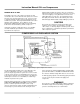
CAP-215 Instruction Manual Oil-Less Compressors 8.1.1. Natural ventilation As warm air rises, adequate wall openings should be provided for cooling air intake (next to the floor) and for cooling air outlet (next to/ in the ceiling). The compressor should be positioned right next to the air inlet opening. Fig. 16: Installation with natural ventilation A Minimum distance from wall, intake side 1.6405 ft. B Minimum distance from wall, exhaust air side 2.
CAP-215 Instruction Manual Oil-Less Compressors 8.1.2. Forced ventilation Forced ventilation facilitates a reduced variation in temperature. It is achieved, for example by using an exhaust air fan. The following information is to determine the size of the exhaust air fan: V = required cooling air stream in ft3/h for a drop in temperature of 18°F p = ∆p = resistance in pa.
CAP-215 Instruction Manual Oil-Less Compressors 8.2. ELECTRICAL INSTALLATION For installation of electrical equipment attend to the following: Follow the National Electric Code or local Electric code in providing, fusing, and disconnect switches. Check electrical supply for voltage, phase, and frequency to see that they match the nameplate stampings on the motor, magnetic starter solenoids, and other control devices. Ensure correct installation is carried out only by qualified personnel only.
CAP-215 Instruction Manual Oil-Less Compressors 9. MAINTENANCE SCHEDULE 9.1.
CAP-215 Instruction Manual Oil-Less Compressors 10. STORAGE, PRESERVATION 10.1. GENERAL If the oil-less compressor is to be put out of service for more than six months, the unit should be preserved in accordance with the following instructions: Make sure the compressor is kept indoors in a dry, dust free room. Only cover the compressor with plastic if it is certain that no condensation will form under the sheet.
CAP-215 Instruction Manual Oil-Less Compressors 11. REPAIR INSTRUCTIONS 11.1. GENERAL Preventive maintenance usually involves replacing the gaskets and sealing rings as well as carrying out the maintenance work. Repair work can be carried out on the oil-less compressor to a certain extent, however certain repair work requires experience and skill.
CAP-215 Instruction Manual Oil-Less Compressors 12.
CAP-215 Instruction Manual Oil-Less Compressors 13. TABLES 13.1. TIGHTENING TORQUE VALUES Unless otherwise specified in text, the following torque values apply. All valve head screws require torque wrench tightening! The torque values indicated are valid for bolts in greased condition. Replace self-retaining nuts on reassembly Bolt or Screw Hex and allen head Hex and allen head Hex and allen head Hex and allen head Hex and allen head Pipe connections (swivel nuts): 13.2.
CAP-215 Instruction Manual Oil-Less Compressors NOTE: Please refer to Chapter 9 of instruction manual for maintenance schedule.
CAP-215 Instruction Manual Oil-Less Compressors 13. MAINTENANCE RECORD NOTE: Please refer to Chapter 9 of instruction manual for maintenance schedule.
CAP-215 Fig.
CAP-215 Fig.
CAP-215 Fig.
CAP-215 Cylinder, Piston and Intake Valve Spare parts sets Class Pos. Part No. 0 2 5 1 CCC1512 2 CCC1513 3 9 3 CCC1466 4 CCC1619 5 CCC1555 6 CCC1554 7 CCC1634 3 9 8 CCC1468 9 CCC1565 10 CCC1566 11 CCC1552 12 CCC1536 13 CCC1637 14 CCC1642 15 CCC1624 16 CCC1610 Fig. 22 Cylinder, piston and intake valve D51.2 Weight Designation Dimensions (kg) Cylinder and piston assembly Ø85 Piston assembly Intake valve assembly Countersunk screw Fixation nut Reed valve Cylinder pin 2m 6 x 4 lg.
CAP-215 Cylinder, Piston and Intake Valve Spare parts sets Class Pos. Part No. 0 2 5 1 CCC1512 2 CCC1513 2 6 3 CCC1466 4 CCC1619 5 CCC1555 6 CCC1554 7 CCC1634 2 4 8 CCC1468 9 CCC1565 10 CCC1566 11 CCC1552 12 CCC1536 13 CCC1637 14 CCC1642 15 CCC1624 16 CCC1610 Fig. 23 Cylinder, piston and intake valve D52.4 Weight Designation Dimensions (kg) Cylinder and piston assembly Ø85 Piston assembly Intake valve assembly Countersunk screw Fixation nut Reed valve Cylinder pin 2m 6 x 4 lg.
CURTIS – TOLEDO, INC. 1905 KIENLEN AVE., ST. LOUIS, MO 63133 TEL. (314) 383-1300 FAX (314) 381-1439 E-MAIL: CURTISCOMP@AOL.