
Manual
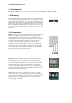

Jumper Settings
For Zone 1 to operate as a master zone the following steps must be adhered
to:
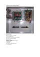
5 Zone Panel
Step 1
The following jumpers should be enabled for zone 1 to act as a master:
J16, J18, J19
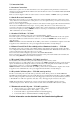
Jumpers J20 – J24 configure zones 1-5 respectively to operate alongside
zone one.
E.g Jumper J23 will enable zones 2-4 to act in tandem with the master zone.
Therefore zone 5 will remain operating independently.
Step 2
Remove Jumper J29 – Note there must be no trigger input at terminal J33
(Link1).
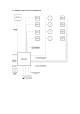
10 Zone Panel
Step 1
The following jumpers should be enabled for zone 1 to act as a master:
Upper circuit board: J16, J18, J15
Jumpers J20 – J24 configure zones 1-5 respectively to operate alongside
zone one. If using more than 5 zones with the master insert a jumper on to
J24 to continue the master on to the lower circuit board.
Lower circuit board: J17
Jumpers J20 – J24 configure zones 6-10 respectively to operate alongside
zone one.
E.g Jumper J23 will enable zones 2-9 to act in tandem with the master zone.
Therefore zone 10 will remain operating independently.
Step 2
Remove Jumper J29 on upper circuit board (zone 1) – Note there must be no
trigger input at terminal J33 (Link1).
Step 3
Connect two cables between circuit board 1 and circuit board 2:
Cable 1: Board 1 Master Connection OUT Master Connection IN Board 2
Cable 2: Board 2 Master Connection OUT Master Connection IN Board 1
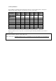
Example for AOV20-10 with zone one as a master. Once step 3 is completed:
Upper board:
J15, J16, J19, J24
Lower Board:
J17, J24.