
Manual

DOC-005J
USER GUIDE – REF. PSF 243
POWER SUPPLY/CHARGER – 24V DC 3 AMP UNIT
General
This power supply unit is for powering a 24V DC 3amp load (2.5 amp load + 0.5 amp charge). It also incorporates a 24V
DC charger for use with Sealed Lead Acid Batteries up to 12ah. If the unit is being used to supply a load and charge
batteries, the total load should not exceed 3 amps. If the unit is being used to supply a load only, without standby
batteries, it is necessary to fit a resistor (value 10k ohm) across the battery terminal block instead of the battery leads to
illuminate the charge fault LED. The unit should be fitted in an upright position on a solid surface using the fixing holes provided.
Supply
Supply to the unit should be 240V ac 50Hz with earth fed to the unit via a 5amp fused outlet fitted adjacent to
the unit. The mains supply in the enclosure should be wired into the fused terminal block next to the PCB. The
unit should be earthed.
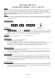
PCB CONNECTIONS
Lid Indicators
Green = Supply Healthy Amber = Fault
When the Green light only is illuminated, the unit is operating normally with supply to the load and the batteries
(when fitted) are receiving charge current. When the Amber light is illuminated at the same time as the Green
light there is a fault on either or both of the output supply and the charge supply. If the Green light is NOT
illuminated, the mains supply is not present or the main “overload” fuse has blown.
PCB Fuses
F.1. Battery = 3Amp quick blow F.2. = 3Amp quick blow
PCB Indicators
Amber (upper) = Short circuit fault/supply fault.
Amber (lower) = Charge output fault.
Upper indicator illuminated, is caused by either a short circuit in the wiring, or an excessive load.
Lower indicator illuminated is caused by a blown fuse (bottom) in the battery charge output (i.e. Short circuit of
the battery leads) or by output supply short circuit. It is essential the battery is not fitted “REVERSE
POLARITY” as this will cause damage to the charging circuit which may be irreparable.
Battery Connections
The typical battery types to be used are Yuasa NP12-7. Two of these in equal state of charge are required to
make up 24V. The supplied leads should be used.
The batteries can be charged faster by fitting the jumper link J5 (on circuit board CUS-256B). This increases
the charge rate by 50%, but because of the 3A total power limit, care should be taken to ensure that the load
does not exceed 2A continuous.
Battery Cut-Out
During A.C. failure the system will switch to battery standby, the output voltage level will follow that of the
batteries down to approximately 19V. At this point the cut-out circuit for lead-acid battery protection will
disconnect power altogether. (circuit board CUS-256B 2006). Should A.C. not be available when testing with
healthy batteries, a temporary short on J11 (board CUS-256B) will activate the battery cut-in to power the load.
(if there is sufficient charge in the batteries)
Fault Relay Option
The fault relay output will go from normal to fault state when A.C. power is removed or when there's a fault in
the unit as indicated by LP2. Sometimes a fault condition may show up if there are temporary excesses in the
total load or if there's a dip in the mains supply. It is advised that the load ciruit be divided and a larger power
supply/charger installed if this situation persists.
J3 J4
J9 J10
FAULT RELAY
BATTERY
OUTPUT
A.C. FROM
TRANSFORMER
J13