User Manual Portable thermal printer s’print www.custom.
All rights reserved. Total or partial reproduction of this manual in whatever form, whether by printed or electronic means, is forbidden. While guaranteeing that the information contained in it has been carefully checked, CUSTOM ENGINEERING SPA and other entities utilized in the realization of this manual bear no responsibility for how the manual is used. Information regarding any errors found in it or suggestions on how it could be improved are appreciated.
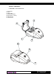
PRINTER COMPONENTS A.
B.
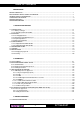
TABLE OF CONTENTS INTRODUCTION MANUAL CONTENTS ...................................................................................................................................... EXPLANATORY NOTES USED IN THIS MANUAL ........................................................................................... GENERAL SAFETY INFORMATION ................................................................................................................ UNPACKING THE PRINTER ......................................
TABLE OF CONTENTS 4. TECHNICAL SPECIFICATIONS 4.1 TECHNICAL SPECIFICATIONS .............................................................................................................. 4-1 4.2 ADAPTOR SPECIFICATIONS ................................................................................................................ 4-4 4.3 DIMENSIONS ......................................................................................................................................... 4-5 5.
INTRODUCTION MANUAL ORGANIZATION In addition to the Introduction which includes a description of the explanatory notes used in the manual, general safety information, how to unpack the printer and a brief description of the printer including its basic features, this manual is organized as follows: Chapter 1: Contains the information required for correct printer installation and its proper use, as well as interface specifications Chapter 2: Contains information on interface specifications Chapter 3: Contains
INTRODUCTION UNPACKING THE PRINTER Remove the printer from its carton being careful not to damage the packing material so that it may be re-used if the printer is to be transported in the future. Make sure that all the components illustrated in fig. 1 are present and that there are no signs of damage. If there are, contact Customer Service. 1. Warning sheet 2. Cable 3. Paper roll 4. Adaptor / Battery recharger 5. Batteries (5 pcs.) 6. Belt coupler 7. Printer 8. Box 1 (Fig.
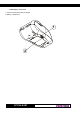
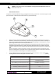
INTRODUCTION NOTE: The 40 column version is downloadable on the Support/Download/Firmware section from www.custom.it web site. (1) PRINTER DESCRIPTION The printers consists of a ABS-V0 casing (1) equipped with a cover (2) under which is housed the paper roll and print mechanism. On the front is the multi-function key (3) and red LED (4). 2 1 3 4 (Fig. 2) • Multi-function key. This key is used to access a variety of printer options depending on how long it is held down.
INTRODUCTION Blank page DPT100-B/I/BT 4
1. INSTALLATION AND USE 1.1 CONNECTIONS 1 (Fig.1.1) 2 1.1.1 Battery Recharger For the Battery Recharger/Power Supply and serial connection, the printer is equipped with a connecting cable (fig. 1.2) that comes packed with the printer and has a double connection system. On one side is a 9-pin female connector (fig. 1.2.A) for the serial port; on the other side of the same connector is a RJ11 connector (fig. 1.2.B) and a jack (fig. 1.2.C) for connection to the battery recharger.
1. INSTALLATION AND USE Turning the printer On and Off using software commands If the printer is off, sending a characters set on the serial line will turn it on (2)(3). Follow the instructions shown in the diagram below: (Fig.1.3) START (2) NOTE It’s not possible to turn on the printer sending one Time out = 10 sec. or more characters through the infrared device. NOTE The printer start up will not occur before 200-250 msec. This delay is caused by internal component.
1. INSTALLATION AND USE (4) NOTE: During the recharge operation it’s not possible turning the printer off. WARNING Incorrect battery recharge voltage (different from that given in tab.1.2) could seriously damage the printer. Tables 1.1 and 1.2 provide specifications for the battery recharger (Tab.1.1) PIN SIGNAL IN / OUT DESCRIPTION 1 + VRIC POWER Battery recharge 2 GND POWER Ground signal Max recharge current 0.6 A Max recharge voltage 12V - 36V (Tab.1.2) 1.2.
1. INSTALLATION AND USE A B 2 (Fig.1.5) 1 • remove the battery pack (2) by lifting the battery removal tape (1) (see fig. 1.6). 2 1 (Fig.1.6) • insert the 5 batteries(7) inside the compartment following the layout indicated in fig. 1.7 and re-position the battery removal tape; (7) Note: when inserting the batteries, make sure the + and – signs are positioned correctly. (Fig.1.7) • reclose the battery compartment by tightening the fastening screws.
1. INSTALLATION AND USE 1.2.4 Disposing of batteries • • • The crossed-out wheeled bin symbol indicates that the disposing of batteries must not be run through the normal cycle of waste disposal. Batteries must be recycled or disposed of properly. Do not throw batteries away as part of normal refuse disposal. Do no throw batteries into open flame! (Fig.1.8) 1.3 CONFIGURATION 1.3.1 Configuration Mod. DPT100-B/I The printer set up print out (see fig. 1.
1. INSTALLATION AND USE (for example 1.5 msec at 9600 bps). The reason is for Half Duplex type of infrared line communication. As a result the Busy condition check must be waited when transmitting data to the printer. If said condition would slow down print-out, it is alternatively possible to transmit the bytes to be printed in fixed length blocks (for example 16 bytes at a time) and to wait for the necessary time to receive a likely XON/XOFF.
1. INSTALLATION AND USE SETUP DEFAULT : Test = NAME = PIN = ADDR = HEAD TEMP. BATT TEMP. HEAD VOLT (Fig.1.10) OK S’print-BT 12345 00:0E:6D:CE:39:8D(13) [°C] = 27.5 [°C] = 25 [V] = 6.
1. INSTALLATION AND USE NOTE: The Name ID is used to diversify one printers from another that have the same name, inside the same area. The index will be added at the end of the name (example: S’print-BT #1). It’s possible that some BlueTooth wireless remote device don’t update immediately printer name, but only at the beginning of new connection.
1. INSTALLATION AND USE (Fig.1.11) 1.6 MAINTENANCE 1.6.1 Changing the paper roll To change the roll of paper, proceed as follows: 1) Open the printer cover (see fig. 1.12) levering on the cover lateral projections and position the paper roll so that it unrolls in the direction shown in figure 1.13; (Fig.1.12) (Fig.1.
1. INSTALLATION AND USE 2) Pull up on the edge of the paper and close the cover (fig. 1.14); (Fig.1.14) 3) Tear off the paper. The printer is now ready (fig.1.15). (Fig.1.15) 1.6.2 Cleaning To clean the printer, use a vacuum cleaner or soft cloth. Before cleaning the printer, unplug its electrical cord and make sure that the printer is off. Do not use alcohol, solvents or hard-bristled brushes. Do not let water or other liquids seep into the printer. (Fig.1.
1. INSTALLATION AND USE 1.6.3 Cleaning the printing head WARNING • Do not touch the head printing line with bare hands or metal objects. • Do not perform any operation inside the printer immediately after printing because the head and motor tend to become very hot. The user is responsible to clean the print head and proceed as follows: • Turn the printer off briefly pressing the multifunction key, located on the front, two times. • Lift the paper compartment cover.
1. INSTALLATION AND USE 1.6.4 Cleaning the rubber roll To clean the rubber roll proceed as follows: • Turn the printer off briefly pressing the multifunction key, located on the front, two times. • Lift the paper compartment cover. • Clean the rubber roll using a medium-stiff brush to avoid them being scratched (see fig. 1.18). • Do not use alcohol or solvents. • Do not let water or other liquids get inside the machine. Alcohol, solvent (Fig.1.
2. INTERFACES (Fig.2.1) 2.1 RS232 SERIAL The printer is equipped with an RS232 serial interface with RJ11 connector (fig. 2.1) located underneath the printer. For serial connection, a connecting cable (fig. 2.2) with double connection system is packed with the printer. On one side is a 9-pin female connector (fig. 2.1.1) to connect to the serial port; on the other side of the same connector is a RJ11 connector (fig. 2.1.2). For the layout of signals on the connectors, please refer to tables 2.1 and 2.2.
2. INTERFACES RJ11 connector DPT100 (fig. 2.1) (Tab.2.1) PIN SIGNAL IN/OUT A DESCRIPTION 1 +VRIC IN - Battery recharge voltage 2 GND - GND Ground signal 3 RX IN TXD Receive data 4 TX OUT RXD Transmit data 5 RTS OUT CTS Ready to send / Ready to receive data 6 GND - GND Ground signal 9-pin female connector (fig. 2.2.A) (Tab.2.2) PIN SIGNAL I N /O U T A D E S C R I P TI O N 1 DCD OUT DCD Data carrier identification.
2. INTERFACES DCD TXD RXD 1 2 3 4 1 2 3 4 5 6 7 8 9 10 11 12 13 14 15 16 17 18 19 20 21 22 23 24 25 CTS DSR SIGNAL GND 5 6 7 8 9 (Fig.2.3) 9-pin connector (s’print cable) PC 2.2 INFRARED BIDIRECTIONAL SERIAL (only DPT100-B model) The printer has a serial interface for bidirectional data exchange. The infrared port is centered on the power part of the front (see fig. 2.4); it uses the encode method bits as described in the IrDA physical layer, for speeds up to 115.
2. INTERFACES It is possible to communicate with the printer in two different ways: by sending a string of characters and/or commands preceded by the IR port Open command and followed by a Close command (standard mode), or by utilizing a simple transfer protocol that guarantees that data is compressed correctly by the printer. 2.2.1 Standard Mode To utilize the printer in standard mode, set the “IR protocol” parameter to Disabled.
2. INTERFACES DATA [LUNG bytes] = data to be communicated to the printer. The datafield may include both data to be printed and command characters (see Section 3 “Printer Functions”). ID JOB [1byte] = ID of the data packet received. The $00 value of this data field is reserved. This number must be different for each transmission: a data packet with the same ID JOB as the previous data packet is formally accepted (an ACK message is transmitted), but it is not interpreted by the printer.
2. INTERFACES ST X $02 LENGT H $08 Data Expanded Line mode Feed $03 $43 $55 $53 $54 $4F $4D C U S T O M $0A IDJOB CKSUM $01 $F3 2.2.3 Printing instructions 1) To use the printer’s infrared port, a computer or Personal Digital Assistant (PDA) with IR port is required. 2) Position a computer conforming to the specifications in point 2) not more than a meter away from the printer’s infrared port.
2. INTERFACES • • • IrCOMM IrMC IrDA Lite Figure 2-6 shows the IrDA data protocol stack and which components are implemented by the printer. (Fig.2.6) Printer Application IrTran-P IrObex IrLan IrMC IrComm(1) LM-IAS Tiny Transport protocol (Tiny TP) IR Link Access Protocol (IrLAP) Asynchronous Synchronous Synchronous Serial IR 4 PPM Serial IR(2) (9600-38400b/s) (1.
2. INTERFACES 2.3.1.2 IrLAP The IrLAP protocol provides: • Management of communication processes on the link between devices. • A device-to-device connection for the reliable, ordered transfer of data. • Device discover procedures. • Hidden node handling. Figure 2-6 identifies the key parts and hierarchy of the IrDA protocols. The bottom layer is the Physical layer, IrPHY. This is the part that converts the serial data to and from pulses of IR light.
2. INTERFACES 2.3.1.4 Link Management-Information Access Service (LM-IAS) Each LM-IAS entity maintains an information data base to provide: • Information on service for other devices that contain the IrDA standard feature (Discovery) • Information on service for the device itself • Remote accessing of another device’s information base This is required so that clients on a remote device can find configuration information needed to access a service. 2.3.1.
2. INTERFACES • 3-Wire raw uses an IAS entry with classname IrDA:IrCOMM and at least two parameters. Its IAS definition may be modified or extended over time. IrLPT has classname IrLPT, only one parameter, and the IAS definition isfixed. IAS entry formats are defined in the next section. Beyond these two distinctions, 3-Wire raw and IrLPT are the same. 2.3.1.5.
2. INTERFACES (Fig.2.10) Printer Application Object Push Profile (OPP) Serial Port Profile (SPP) OBEX SDP RFCOMM L2CAP Host Controller Interface Link Manager Link Controller Radio 2.4.1.1 Serial Port Profile The Serial Port Profile provides RS232 serial cable emulation for Bluetooth wireless technology devices. In this way, legacy applications do not have to be modified to use Bluetooth technology; they can simply treat Bluetooth wireless link as a serial cable link.
2.
3. PRINTER FUNCTIONS 3.1 CONTROL CHARACTERS The command table lists all the commands for the management of the printer functions. These commands can be transmitted to the printer with the serial interface. The commands can be transmitted to the printer at any moment, but they will only be carried out when the characters previously transmitted have been printed or the commands previously transmitted have been carried out.
3. PRINTER FUNCTIONS Com. HEX $1D $57 n d1...dn $1D $F6 (nH) (nL) Com. ASCII GS W n d1...dn GS { } (nH) (nL) Description Prints n byte of a 200 dpi graphic line. Aligns the ticket at the first printed line. The following pages provide a more detailed description of each command.
3.
3.
3. PRINTER FUNCTIONS [Description] [Notes] Enables graphic mode: a line in 24 column mode corresponds to 144 horizontal dots divided into 24 blocks of 6 dots each; a line in 40 column mode corresponds to 240 horizontal dots divided into 40 blocks of 6 dots each. To obtain graphic printing, enter the command $11 at the beginning of each line.
3. PRINTER FUNCTIONS • After the command execution the printer ignores all the characters received from the communication port until to the next $1B $02 reception. • After receiving this command the infrared led is functioning, as usual.
3. PRINTER FUNCTIONS [Notes] [Default] [Reference] [Example] which was enabled at the moment of switching on • Same as hardware reset • After the command has been transmitted, 1.5 seconds elapse before the printer is enabled This can be useful during switching on in order to avoid the sending of false characters during initialization by the master device.
3. PRINTER FUNCTIONS devices ( for example mobile phone), which allow PINs entered, will not support alphanumeric entry, devices sold with fixed PINs should be sold with a note of the PIN given as decimal digits.
3.
3. PRINTER FUNCTIONS [Example] $1B $63 [Name] [Format] [Description] Management of bar code printing ASCII ESC c [code] [height] [position] [options] [length] [data] Hex 1B 63 Decimal 27 99 This command executes a barcode printing depending on the following parameters: [code] = Type of bar code (ASCII character) VALUES: I Interleved 2/5 C Code 39 B CodaBar e EAN8 E EAN13 [height] = Number of dot lines in 1/8 mm units. [position] = Left hand margin, expressed in 1/8 mm units.
3. PRINTER FUNCTIONS Bi t 1 Function Description 6 Not used - 7 Not used - [maximum length] Interleaved 2/5 = 12 characters Code 39 = 10 characters CodaBar = 10 characters EAN8 = 8 characters EAN13 = 13 characters [data] = Expressed in ASCII.
3.
3.
3. PRINTER FUNCTIONS there could be a time lag between command reception and data transmission, depending on data buffer status. [Default] [Reference] [Example] $1D $55 [Name] [Format] Resets the printer parameters to default. ASCII GS U Hex 1D 55 Decimal 29 85 Resets the printer parameters to the default configuration. • After executing this command the printer is initialized. [Description] [Notes] [Default] [Reference] [Example] $1D $57 n d1 ...
3. PRINTER FUNCTIONS [Example] To print a logo on a ticket that is 25 mm long with the hole (or notch) at the end of the ticket, the following command must be sent: $1D, $F6, $FF, $7B (perform alignment) $1B, $FA, $00, $55 (print logo) In this example, nH and nL are expressed in module 2 so that the motor will recede.
4. TECHNICAL SPECIFICATIONS 4.1 TECHNICAL SPECIFICATIONS Table 4.1 gives the main technical specifications for the model DPT 100-B/I. (Tab.4.1) Resolution 203 DPI (8 dot/mm) Paper roll size 57.
4. TECHNICAL SPECIFICATIONS Table 4.2 gives the main technical specifications for the Bluetooth wireless technology model DPT 100-BT. (Tab.4.2) Resolution 203 DPI (8 dot/mm) Paper roll size Recommended types of paper 57.
4. TECHNICAL SPECIFICATIONS (Tab.4.3) 57 mm paper 12.7 cpi Number of columns 24, 40 (3) Characters (L x H mm) Normal 2x3 Double height 2x6 Double width 4x3 Double height and width 4x6 Bidirectional infrared port specifications Operating distance up to 1mt. Wave length 800-900 nm Bluetooth port specifications Operating distance BlueTooth specification up to 10 mt. vers. 1.
4. TECHNICAL SPECIFICATIONS 4.2 ADAPTOR SPECIFICATIONS 220Vac Adaptor (Tab.4.4) Input spe cifications Input voltage 230 Vac Input frequence 50 H z Output spe cifications Output voltage 18 Vdc 120Vac Adaptor (Tab.4.
4. TECHNICAL SPECIFICATIONS 4.3 DIMENSIONS 75 Printer dimensions are shown below. 88,2 R (Fig.4.
4.
5. CHARACTER SETS 5.1 CHARACTER SETS The printer has a 224-character font, a print-out of which is shown below. (Fig.5.
5.
APPENDIX A - ACCESSORIES AND SPARE PARTS A.1 TICKET ALIGNMENT A.1.1 Ticket alignment (Fig.A.1) 4 1,5 7 57 54 1,5 Paper stock with alignment marks is permitted so that tickets of a fixed length or with pre-printed areas may be utilized.
APPENDIX A - ACCESSORIES AND SPARE PARTS A.1.2 Alignment Description The $1D $F6 command searches for the reference notch on the paper and move the label with the value of nH e nL parameters. For move in the exact point for printing on the label just give the right values to parameters nH and nL. Example: To print a logo on a ticket like in to fig.
APPENDIX A - ACCESSORIES AND SPARE PARTS A.2 ACCESSORIES A.2.1 Belt coupler In the s’print-B battery model, there is a support kit available for the printer that consists of a belt and fastening screws. The figure below illustrates how the belt coupler is attached underneath the printer. (Fig.A.3) A.3 SPARE PARTS (Tab.A.2) RCT57X50 Roll of the rm al pape r BTNIMH-1.