GE Consumer & Industrial Technical Service Guide June 2007 Profile Side-By-Side Refrigerators PSF26PGWBB PSS26PSWSS PSC25PSWSS PSW26RSWSS 31-9153 9153 GE Appliances General Electric Company Louisville, Kentucky 40225 HOME WATER HELP CRUSHED LOCK CUBED
IMPORTANT SAFETY NOTICE The information in this service guide is intended for use by individuals possessing adequate backgrounds of electrical, electronic, and mechanical experience. Any attempt to repair a major ap pli ance may result in personal injury and property damage. The manufacturer or seller cannot be responsible for the interpretation of this information, nor can it assume any liability in connection with its use.
Table of Contents 3-Way Valve ..................................................................................................................................................................... 40 Beverage Center Blower Motor ............................................................................................................................... 30 Check Valve .............................................................................................................................................
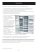
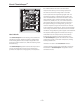
Introduction *This new Profile Side by Side dual evaporator refrigerator has the following features: • New integrated dispenser with LED lighting, child lock, and door alarm combined with LCD screen provides customer control of temperatures and features presented in computer-style menus. • Separate freezer and fresh food evaporators with independent cooling. • No damper/air inlet assembly in the fresh food section creates more usable space on the top shelf.
About ClimateKeeperTM the airflow between the fresh food and freezer compartments during normal cooling operations.* This ensures that the humidity levels in the fresh food compartment are significantly higher than in a conventional system,** allowing fresh produce and other unsealed foods to retain their moisture content and freshness longer. Moisture sensitive foods such as fresh fruit, salads, rice, etc., can now be stored on open shelves without excessive moisture loss.
Technical Data 8AC0=C B054CH =>C824 38B2>==42C ?>F4A 2>A3 145>A4 B4AE828=6 8AC0=C A42>==42C 0;; 6A>D=38=6 34E824B 0[[ _Pacb ^U cWXb P__[XP]RT RP_PQ[T ^U R^]SdRcX]V T[TRcaXRP[ RdaaT]c PaT Va^d]STS 8U Va^d]SX]V fXaTb bRaTfb bcaP_b R[X_b ]dcb ^a fPbWTab dbTS c^ R^\_[TcT P _PcW c^ Va^d]S PaT aT\^eTS U^a bTaeXRT cWTh \dbc QT aTcda]TS c^ cWTXa ^aXVX]P[ _^bXcX^] P]S _a^_Ta[h UPbcT]TS CWXb X]U^a\PcX^] Xb X]cT]STS U^a dbT Qh X]SXeXSdP[b _^b bTbbX]V PST`dPcT QPRZVa^d]Sb ^U T[TRcaXRP[ T[TRca^]
Nomenclature P S F 26 P G W B B Exterior Color WW - White on White BB - Black on Black Brand/Product P - Profile Configuration S - Side by Side Model Year W - 2007 Depth/Power H - Inverter Compressor/Energy Star S - Standard Depth C - Counter Depth F - High Gloss Smooth W - Full Wrap Icemaker/Exterior G - 1-Year Filter Cubed/Crushed Interior Features/Shelves P - Dual Evaporator R - Dual Evaporator New Appearance Capacity (cubic feet) AHAM Rated Volume The nomenclature plate is located on the upper righ
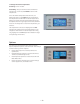
Control Features About the home screen The Home screen is the initial screen presented after power-up. The status bar at the top displays the status of many of the refrigerator features. Freezer and Refrigerator sections display present compartment temperatures. Not all features are on all models. • Press displayed set temperatures. Set temperatures then can be changed. • Press the light icon to operate the dispenser LED.
To change the Freezer temperature: Access By: Home > Freezer Activate By: Using the arrows to select the desired temperature. You must press ENTER to set the new temperature. Once the desired temperature has been set, the display will return to the HOME screen and show the set temperatures underneath the actual temperature display for several seconds. Several adjustments may be required. Each time you adjust the controls, allow 24 hours for the refrigerator to reach the temperature you have set.
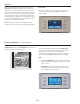
Quick Ice How to Use When you need to speed up ice production, use the Quick Ice feature. While this feature is turned on, the freezer fan runs continuously for 48 hours, or until the feature is turned OFF. During this period, ice production will increase up to 40% (up to 2 lbs/day). Models with the integrated ice feature system require at FIRST USE at least half an 8 oz. glass of ice to be dispensed every 6 to 12 hours. This will help the icemaker fill the bucket properly so that dispensing is better.
About CustomCoolTM (on some models) How it Works The CustomCool™ feature is used to quickly chill items, thaw items, or hold the pan at a specific temperature. This feature is a system of dampers, a fan, a temperature thermistor, and a heater. The pan is tightly sealed to prevent temperature fluctuations in the rest of the refrigerator. The controls for this pan are located on the dispenser with the temperature controls. How to Use Empty the pan. Place the Chill/Thaw tray in the pan.
About TurboCoolTM How it Works How to Use TurboCool™ rapidly cools the refrigerator compartment in order to more quickly cool foods. Use TurboCool when adding a large amount of food to the refrigerator compartment, putting away foods after they have been sitting out at room temperature or when putting away warm leftovers. It can also be used if the refrigerator has been without power for an extended period.
Precise Fill (on some models) This water dispenser is equipped with a feature called “precise fill.” This feature allows you to choose a precise amount of water (cups, ounces, pints, or liters) that you would like dispensed. Access by pressing: Home > Options > Dispenser Options > Precise Fill > Set Amount. Activate by using the arrow buttons to select the desired amount. Press MORE UNITS to select between CUPS, OUNCES, PINTS or LITERS. Select the precise amount of water you would like dispensed.
Information and Settings Use Information and Settings to access Settings, Screen Appearances, and Feature Info. Access by: Home> Options> Information and Settings. • Press Settings to access Button Beep, Door Alarm, Units Metric/English, and Cooling System Off. • Press Screen Appearance to access Color Options, Brightness, and Screen Saver.
Feature Info Access by: Home> Options> Information and Settings> Feature Info. Features will access information related to: • Precise Fill • CustomCool™ • QuickFreeze™ • LCD Screen Colors • Beverage Center • Temperature Set • Quick Ice • TurboCool™ About the help screen The Help screen provides General information and guidance to certain features of the refrigerator. The help screen can also provide help regarding the Current screen displayed. To access Help, press the Help pad.
Demo Mode The LCD screen has a DEMO MODE that can be accessed. To enter the DEMO Mode press the HOME and HELP pads simultaneously for 3 seconds. Upon entering, the cooling system will turn off. The VIEW FEATURE selection provides a description and instructions on how to use 8 features of the refrigerator. The 8 features presented are Precise Fill, CustomCoolTM, QuickFreezeTM, LCD Screen Colors, Beverage Center, Temperature Set, Quick Ice, and TurboCoolTM.
Replacing the light bulbs. Setting the controls to OFF does not remove power to the light circuit. Reveal® appliance bulbs are used on some models. They can be identified by their blue color when they are not illuminated. Not all features are on all models. Your light shield will look like one of the following. Tabs OR Pocket O LD LD Unplug the refrigerator. The bulbs are located at the top of the compartment, inside the light shield.
Dispenser LED Light If the lock is engaged when the filter timer expires, the LED will come on but cannot be reset until the lock is turned off. The LIGHT selection on the LCD screen turns the dispenser LED lights on and off. When the light selection is turned off, the LEDs will fade out. The dispenser LEDs will come on automatically when the dispenser cradle is pressed and will fade out approximately 5 seconds after it is released. The LIGHT selection will not turn off the LEDs during dispensing.
About the refrigerator doors. Door Closure Mechanism The closure mechanism consists of a lever, attached with a spring to a hook in the base channel, which interacts with a cam mounted to the bottom of each door with two T-20 Torx screws. A pair of pliers can be used to remove the spring from the hook. The spring and lever can then be pulled out through the hole in the base channel. Hook Cam Lever Spring Roller Door Alignment If doors are uneven, adjust the refrigerator door. 1. Using a 7/16-in.
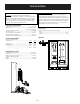
Components Locator Views Rear View (Non-Inverter model shown) Main Control Board 3-Way Valve Compressor Water Valve Condenser Fan Condenser Dryer Jumper Tube Rear View (Inverter model shown with drain tube and selected wiring removed for clearer view.
Check Valve 1 Front View Over-Temp Thermostat Note: The check valve is part of the freezer evaporator and is not available separately.
Refrigeration System Fresh Food Section Cooling Condenser Fan Running Freezer Fan Off * Fresh Food Fan Running *Note: Variable speed compressors have an accumulator. Single-speed compressors do not have an accumulator. Freezer Section Cooling Condenser Fan Running Freezer Fan Running * Fresh Food Fan Off *Note: Variable speed compressors have an accumulator. Single-speed compressors do not have an accumulator.
Fresh Food and Freezer Section Cooling Condenser Fan Running Freezer Fan Running * Fresh Food Running *Note: Variable speed compressors have an accumulator. Single-speed compressors do not have an accumulator.
Evacuation and Charging Procedure Refer to Service Guide #31-9118 for complete instruction on replacing the freezer & fresh food evaporators. Refer to Service Guide #31-9067 for complete instructions on using the LOKRING method of installing an evaporator. WARNING: • Be careful when using a torch inside the plastic cabinet. Use approved safety equipment and protect the liner from damage with the heat shield kit (part #WX5X8926) which includes the heat shield and thermal paste.
Components Freezer Evaporator The following components must be removed in the appropriate order to access the freezer evaporator: 5. Rotate the icemaker to the right, then pull the left side towards the front to disengage it from the 2 posts. 1. Unplug the refrigerator. 2. Remove the ice bucket, shelves, and drawers. Post 3. Using a small flat-blade screwdriver, expand the 2 clips and disconnect the icemaker wire harness from the auger motor assembly. Post Icemaker Wire Harness 6.
9. Lift the fan housing up, pull it forward, and disconnect the wire harness. 14. Unclip the light bulb sockets from their mounting holes and disconnect the sockets. 10. Remove the two ¼-in. hex-head screws that attach each mounting bracket. Wire Harness (Continued next page) Note: The evaporator cover is held in place by four ¼-in. hex-head screws and 2 top tabs. The tabs are inserted into recessed slots in the bottom of the evaporator fan plenum. 15.
19. Press inward on the 2 tabs and release the auger motor assembly wire harness receptacle from the evaporator fan plenum. 21. Unclip the evaporator thermistor and ground wires from the evaporator. 22. Remove the two ¼-in. hex-head screws from the fan bracket. Thermistor 20. Remove the 4 hex-head screws that hold the evaporator fan plenum in place (Fig. 1 and Fig. 2). Ground Wires 23. Peel back the tape then slide out the wiring grommets from the fan bracket. 24. Remove the fan bracket.
5. Carefully pull the cover forward, then disconnect the fresh food evaporator fan and beverage center blower. Fresh Food Evaporator The following components must be removed in the appropriate order to access the fresh food evaporator: 1. Remove the CustomCool™ drawer, and necessary drawers and covers above the CustomCool drawer, to expose the evaporator cover. Disconnect Disconnect Fresh Food Evaporator Fan Note: The water line coil cover is slotted.
Fresh Food Evaporator Fan Check Valve A variable speed 12-VDC motor is mounted in front of the fresh food evaporator. The fan, the blower, and evaporator cover are replaced as a complete assembly. Check Valve • A nylon piston inside the check valve floats back and forth, depending upon refrigerant flow. • The check valve prevents refrigerant from flowing back into the freezer evaporator.
For testing, the beverage center blower motor can be run for short periods using a 9-volt battery. Beverage Center Blower Motor A 12-VDC blower motor is mounted inside the fresh food evaporator fan housing. The blower motor, evaporator fan, and evaporator cover are replaced as a complete assembly. Note: Unless turned off at the control, the beverage center feature will remain active for 6 months. Press the Beverage Center pad to restart.
Freezer Evaporator Fan The position of the fan blade in relation to the shroud is important. 5/16" ± 0.03 Blade tip 1.0" ± 0.05 Target Orifice Air Flow Motor The evaporator fan is the same fan used on previous models; however, a significant difference is that the main control board neither requires nor receives input from the fan feedback/rpm (blue) wire. The fan utilizes a permanent magnet, 4-pole, DC motor that operates at 3 different speeds: high, medium, and low.
QuickFreeze™ Fan Motor Condenser Fan A 12-VDC motor is mounted in front of the freezer evaporator cover. The fan motor and fan housing are replaced as a complete assembly. The fan is mounted in the machine compartment with the no-clean condenser. The fan and fan shroud are mounted on one end of the condenser, and the other end of the condenser is blocked. When the fan is operating, air is pulled from the center of the condenser, drawing air in through the coils.
The condenser fan is mounted with screws to a fan shroud and mounting bracket that is attached to the condenser. To access the condenser fan motor, disconnect power from the refrigerator and remove the machine compartment cover. Depending on the model, use one of these two methods to remove the condenser fan motor from the refrigerator. Method #1: 1. Disconnect the condenser fan plug, then remove the ¼-in. hex-head screw from the upper corner (closest to you). 2.
Fresh Food and Freezer Thermistors Thermistors The fresh food and freezer thermistors (part # WR55X10025) are located in the mullion dividing the fresh food and freezer compartments. Temperature (°C) Resistance in KiloOhms -40 -40 166.8 kΩ -31 -35 120.5 kΩ -22 -30 88 kΩ -13 -25 65 kΩ -4 -20 48.4 kΩ 5 -15 36.4 kΩ 14 -10 27.6 kΩ 23 -5 21 kΩ 32 0 16.3 kΩ 41 5 12.7 kΩ 50 10 10 kΩ 59 15 7.8 kΩ 68 20 6.2 kΩ 77 25 5 kΩ 86 30 4 kΩ 95 35 3.2 kΩ 104 40 2.
Fresh Food Evaporator Thermistor The fresh food evaporator thermistor (part # WR55X10025) is located in an aluminum thermal block on the back of the evaporator. It is attached to the fresh food evaporator by a wire tie. (See Fresh Food Evaporator for accessing instructions.) Insert the new thermistor into the thermal block. Add RTV102 silicone to hold the thermistor in place. Make certain to wire tie the thermal block back to the evaporator.
The system is designed to run the fan until the fresh food evaporator thermistor reaches 35°F. Once this temperature is reached, the fan continues to run for an additional 5 minutes. Under normal conditions, the defrost time takes approximately 30 minutes. The maximum time the fan runs in low speed is 60 minutes. If the evaporator thermistor has not reached 35°F after 60 minutes, the control switches to extended defrost #1.
6. Lift and rotate the inverter counterclockwise. Inverter The inverter is accessed from the back of the refrigerator and is located on the left side of the compressor behind the water valve. The water valve must be removed to access the inverter. 7. Disconnect the compressor harness from the compressor terminals. Lip To remove the Inverter: Disconnect 1. Disconnect power to the refrigerator and remove the back access panel. Tab 2. Remove the ¼-in.
Low speed (1710 rpm) - 57 Hz • Medium speed (2100 rpm) - 70 Hz • High speed (3120 rpm) - 104 Hz The inverter receives commands from the main control board (red and white wires). The main control board will send a pulse width modulation run signal from the J15 connector of between 4-6 VDC effective voltage to the inverter (all wires must be connected). The inverter will select compressor speed (voltage output) based on this signal.
• 3°F to 5°F above refrigerator set point - medium speed. • 5.5°F to 7°F above refrigerator set point - high speed. Single-Speed Compressor The compressor is a reciprocating type. Refer to the mini-manual for the BTU/hour rating and the compressor capacity test specification. Note: The compressor will run at medium speed if the freezer temperature is 20°F or more above the setpoint.
3-Way Valve Coil 3-Way Valve The 3-way valve is located beneath the main control board in the machine compartment and is accessed from the back of the refrigerator. It is composed of a magnetic coil and a valve body. Two ¼-in. hex-head screws mount the valve to the cabinet. • Make certain that rubber gaskets are installed on mounting bracket to reduce vibration. The 3-way valve coil receives 12-VDC pulses from the main board to change the position of the valve.
3-Way Valve Body Valve Rotation • The valve body contains a cam, rotor, and magnet. • The pulses of the valve coil cause the magnet to rotate inside the valve body. • The rotor and cam are grooved to rotate with the magnet. • As the magnet rotates, it moves the cam at the bottom of the valve. • The entire valve body has refrigerant flowing through it when the compressor is operating. • Use care not to damage the top of the valve body when installing the coil on the valve.
Testing the 3-Way Valve Replacing the 3-Way Valve The valve returns to “home” at the end of every freezer defrost cycle and whenever the refrigerator is reconnected to power. To test the valve, disconnect the refrigerator from power for at least 10 seconds, place a finger on top of the valve, and reconnect power. The main control overdrives the valve to the “home” position. You should be able to feel the valve vibrate as the coil moves the magnet to the home position .
1. Unplug the refrigerator. 2. Remove the rear access cover and evacuate the sealed system. (See Evacuation and Charging Procedure.) 3. Remove the valve body from the valve coil by carefully pressing down on top of the valve body. 5. Connect the new jumper tube to the inlet tube of the new 3-way valve. 6. Prepare the taped capillary tube, and insert it into the 3-way valve freezer outlet port (identified with black mark or tape). 7.
9. Angle the torch so the flame is not directed towards the valve body when brazing the three joints. 10. Remove the thermal paste residue and dry the valve body thoroughly. Install the valve body into the coil. Note: If necessary, use an adjustable pliers to carefully install the valve body into the coil. DO NOT depress on the top of the valve body. See photo. CustomCool™ Assembly Note: Refer to Service Guide #31-9075 for complete instruction on servicing CustomCool™ components.
6. Remove the support from under the evaporator tubing. 7. Remove the 3 Phillips-head screws that hold the CustomCool™ unit to the bottom of the refrigerator compartment. 9. Place the unit vertically on its right side. 10. Peel back the foam seal from the left side and the tape from the rear of the unit. Tape Support Foam Seal 11. Release the 3 tabs and remove the cover. 8. Move the unit to the right, then carefully pull the left side towards the front of the refrigerator.
The dispenser shield can be removed to access the cradle switch, duct door, duct door solenoid, and dispenser LED lights. The dispenser shield is attached to the dispenser recess with 4 Phillipshead screws. Dispenser Assembly The dispenser assembly consists of the interface, display board, dispenser shield, and duct door functioning parts. The dispenser interface can be removed to access the display board and the dispenser shield mounting screws.
Precise Fill The Precise Fill mode allows the user to select a specific volume to be dispensed in either cups, ounces, pints, or liters. Overview The Precise Fill design places a flowmeter between the water valve and the dispenser to measure water flow through the system. The flowmeter sends a signal to the main control board. The main control interprets the signal, turning the water valve off at the appropriate time. The quantity dispensed is displayed on the dispenser board.
Flowmeter 3. Remove the ¼-in. hex-head screw from the flowmeter bracket. The flowmeter is located in the machine compartment behind the water valve. The water valve must be removed to access the flowmeter. Inlet Tube 4. Lift and rotate the flowmeter bracket counterclockwise to disengage the 2 tabs at the top of the bracket. Outlet Tube 5. Carefully pull out the bracket and flowmeter. To remove the flowmeter: 6. Disconnect the water lines from the flowmeter.
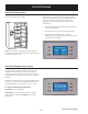
Troubleshooting Control Diagnostics Using LCD Screen The LCD screen has a self-diagnosis mode that can be accessed and will assist the technician to test certain functions of the LCD screen, dispenser, and interior fans. This mode can aid the service technician in quickly identifying failed or improper operation of certain components and systems. Control diagnostics using the LCD screen do not use error codes to identify problems.
Diagnostics Aid Kit The diagnostic aid kit may assist the technician to functionally test individual components. A diagnostic aid kit can be assembled and consists of a key pad temperature control assembly and wire harness. The parts required are WR55X10390 and WX05X14999. Using the kit, diagnostics can be performed by removing the base grill and plugging into the diagnostic aid wire harness located on the left side.
Freezer Display Fresh Food Display 0 7 Diagnostics Results Control and Sensor System Test Checks each thermistor in order. 1 0 Dampers Test Custom Cool™ damper will open, close after 10 seconds, pause briefly, then single damper will open for 10 seconds. 1 1 Fan Test Cycles through each fan for 5 seconds. 1 2 100% Run Time Sealed system on 100% of the time. Times out after 1 hour. 1 3 Prechill Test Starts prechill mode. Unit returns to normal on its own.
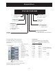
Control Board Connector Locator Main Control Board J13 J10 J4 J15 J8 J14 J9 J3 J11 J2 K4 J7 K5 J12 J1 J5 K1 K2 K3 J10 and J13 - Earth (Ground) J4 - LCD Board J8 - Line (L1) to AC Compressor* J3 - QuickFreeze™ Fan, Beverage Center Fan, 3-way Valve J9 - Defrost Heater J11 - Line (L1) J7 - Neutral, Door Switches, CustomCool™ Heater, Water Valve, Cube Solenoid, Auger Motor J1 - Fresh Food Thermistor, Freezer Thermistor, Fresh Food Evaporator Thermistor, Freezer Evaporator Thermistor, Model Sel
– 53 – FZ Door Switch FF Door Switch Custom Cool Heater Auger Motor Interlock Water Valve Crusher Solenoid Auger Motor Neutral J10 1 J11 K1 Not Used J12 K2 CRUSHER K5 DEFROST K4 K7 NOT USED CUSTOM COOL K3 WATER Duct Heater Line (L1) Line (L1) to AC Compressor J8 (Not Used for Inverter Compressor, Wire Ends in Cabinet) J9 Defrost Heater J18 AUGER J7 EARTH 2 J6 1 J19 +5V Custom Cool Thermistor Custom Cool Dual Damper + Custom Cool Dual Damper Custom Cool Single Damper + Custom Cool S
MAIN CONTROL BOARD TROUBLESHOOTING The main control board is located at the back of the refrigerator, above the machine compartment on the right-hand side. (See Control Board Connector Locator.) CONTROL BOARD PIN DEFINITIONS CONNECTOR J1 J1 J1 J1 J1 J1 J1 J1 J1 PIN INPUT OUTPUT FUNCTION 1 VDC Feedback of fresh food evaporator thermistor value. Thermistor value is NTC (when temperature drops, resistance value increases), causing return voltage reduction.
CONTROL BOARD PIN DEFINITIONS CONNECTOR J2 J2 J2 J2 J2 J2 J2 J2 PIN INPUT OUTPUT FUNCTION Feedback from evaporator fan. Evaporator fan feedback is not 1 HZ read for this application. Model pin selection. 2 VDC 3 VDC Evaporator fan and condenser fan common. 4 VDC Output to evaporator fan for motor operation. Effective voltage is determined by pulse width modulation. 5 VDC Output to condenser fan for motor operation. Effective voltage is determined by pulse width modulation.
CONTROL BOARD PIN DEFINITIONSS CONNECTOR PIN J5 1 J5 2 J5 3 J5 4 J5 5 J5 6 INPUT OUTPUT FUNCTION VDC VDC ExpressChill (CustomCool™) damper. VDC VDC ExpressChill (CustomCool™) damper. VDC VDC ExpressChill (CustomCool™) damper. VDC VDC ExpressChill (CustomCool™) damper. VDC Provides 5 VDC for ExpressChill (CustomCool™) thermistor. VDC Feedback of ExpressChill™ (CustomCool™) thermistor. Thermistor is NTC (when temperature drops, resistance value increases), causing return voltage reduction.
CONTROL BOARD PIN DEFINITIONS CONNECTOR J9 PIN 1 INPUT OUTPUT FUNCTION VAC Switched L1 voltage to the defrost circuit - 120 VAC. A timer (main control software), counts how long this circuit is energized and uses this information to determine if the next defrost cycle is adaptive or nonadaptive. CONTROL BOARD PIN DEFINITIONS CONNECTOR PIN J11 1 INPUT OUTPUT FUNCTION VAC Constant L1 voltage to control board circuits - 120 VAC input potential for switched L1 terminals.
Main Control Board J2 Connector (Low-Voltage DC Side) Blue/White White/Silver Component Termination Evaporator fan tachometer Model Fan Common Input Common 4 Yellow/Black Evaporator fan Output 5 Yellow Condenser fan Output 6 Black/White Fresh food fan Common 7 Tan Common 8 Red CustomCool™ fan Fan supply voltage (12 VDC) Pin Wire Color 1 Blue 2 3 Input/ Output Pin-to-Pin Voltage Reading Input Not applicable to this model.
Main Control Board J4 Connector (Low-Voltage DC Side) Pin Wire Color 1 2 3 Black Red Blue Component Termination Temperature control Temperature control Temperature control Input/ Output Communication Output Common Pin-to-Pin Voltage Reading 2-way digital communication J4 pin 2 to pin 3 = 12 VDC J4 pin 2 to pin 3 = 12 VDC J4 Comm. 2-Way Digital Comm. +12V Comm.
Main Control Board J8 Connector (High-Voltage Side) Pin Wire Color J8 Black Component Termination Compressor Input/ Output Output Pin-to-Pin Voltage Reading J8 to J7 pin 9 = 120 VAC J10 EARTH Line (L1) to AC Compressor J8 (Not Used for Inverter Compressor, Wire Ends in Cabinet) J9 Defrost Heater 120 VAC Line (L1) J7 Neutral FZ Door Switch FF Door Switch Custom Cool Heater Auger Motor Interlock Water Valve Crusher Solenoid Auger Motor J18 Low Voltage DC J11 K4 K5 Not Used J12 Duct Heater 1
Main Control Board J11 Connector (High-Voltage Side) Pin Wire Color J11 Brown Component Termination L1 Input Input/ Output Input Pin-to-Pin Voltage Reading J 11 to J7 pin 9 = 120 VAC J10 EARTH Line (L1) to AC Compressor J8 (Not Used for Inverter Compressor, Wire Ends in Cabinet) J9 Defrost Heater 120 VAC Line (L1) J7 Neutral FZ Door Switch FF Door Switch Custom Cool Heater Auger Motor Interlock Water Valve Crusher Solenoid Auger Motor J18 Low Voltage DC J11 K4 K5 Not Used J12 Duct Heater
– 62 – Yes Is there 6.5 -7 VDC between red and white wires on flowmeter when 1st activated Yes No No No No Is there 13.6 VDC between red and black wires on J4 at dispenser board Yes Check: 1.) Wiring between dispenser and main control board 2.) Wire connector at bottom of freezer door 3.) Main control board Yes No Does dispenser display light up? NO PRECISE FILL WATER Check: 1.) Wiring between flowmeter and main control board 2.) Main control board Replace flowmeter Check: 1.
Icemaker Service Test Mode The electronic icemaker has a service test mode that can be utilized by the service technician in order to test basic operation of the icemaker. The service test mode consists of a harvest cycle followed immediately by a water fill. The harvest cycle is entered, regardless of icemaker temperature or arm position. To enter the service test mode: 1. Turn the power switch to the off position and wait 20 seconds. (The green power light will be unlit.) 2.
VALVE 197D5678G001 FLOW METER WHITE BLUE BLACK RED J4-3 BLACK J4-2 J4-1 BLACK WHITE + GRAY YELLOW RED ORANGE VALVE, 197D5678G001 RED SMART TROLLEY YELLOW WHITE RED DEP LED BLACK J3-10 J3-9 J3-8 J3-7 J3-6 J14-2 J14-4 SMART TROLLEY RED DEP SWITCH 1 TO HTR RED EVAP.
( ( !) & $ ) & ' $ $ ) & $ * * !) $ " %) & !$ % $& &$! * * !) ) & $ " %) & $ ! * !) & $ %&!$ ' $ * !) $ ) & ' ) & * !) " $!) ' " $ % " $ ) "" ) & $ ( ' * !) ' #' $ + '
Warranty All warranty service provided by our Factory Service Centers, or an authorized Customer Care® technician. To schedule service, on-line, 24 hours a day, visit us at ge.com, or call 800.GE.CARES (800.432.2737). Please have serial number and model number available when calling for service. For The Period Of: Staple your receipt here. Proof of the original purchase date is needed to obtain service under the warranty.