
User's Guide

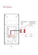
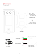
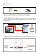
Table Of Contents
- 슬라이드 번호 1
- 슬라이드 번호 2
- 슬라이드 번호 3
- 슬라이드 번호 4
- 슬라이드 번호 5
- 슬라이드 번호 6
- 슬라이드 번호 7
- 슬라이드 번호 8
- 슬라이드 번호 9
- 슬라이드 번호 10
- 슬라이드 번호 11
- 슬라이드 번호 12
- 슬라이드 번호 13
- 슬라이드 번호 14
- 슬라이드 번호 15
- 슬라이드 번호 16
- 슬라이드 번호 17
- 슬라이드 번호 18
- 슬라이드 번호 19
- 슬라이드 번호 20
- 슬라이드 번호 21
- 슬라이드 번호 22
- 슬라이드 번호 23
- 슬라이드 번호 24
- 슬라이드 번호 25
- 슬라이드 번호 26
- 슬라이드 번호 27
- 슬라이드 번호 28
- 슬라이드 번호 29
- 슬라이드 번호 30
- 슬라이드 번호 31
- 슬라이드 번호 32
- 슬라이드 번호 33
- 슬라이드 번호 34
- 슬라이드 번호 35

5
1. Connect the power cable to the adapter. (Maximum consumption power = 0.5A@12V)
2. The door lock cable is for connecting the door lock (deadbolt, EM lock) and EXIT-button.
3. Connect the yellow and black cable to the exit button.
4. Connect the red cable of the door lock cable to the exit button of the door lock. (Relay contact provided)
5. If there is a door open signal output on the deadbolt (EM lock), connect it to the orange color cable (for
door monitoring input).
Cable Connection
1.3
6. Open the cover on the back of the Face A+ and connect the prepared power cable and door lock cable
to the corresponding connectors.
7. In addition, when interworking with the manager server, the LAN cable must be connected to the RJ45
port.
▶ Power Cable
1 Red: 12V
2 Black: GND
3 Green : TBD
4 Yellow : TBD
▶ Door-Lock Cable Pin-Map
1 Yellow: EXIT Button (Input)
2 Black: EXIT Button (GND)
3 Orange : Door Monitoring
4 Red: Relay (NO)
5 Red: Relay (COM)
Terminal1
Terminal2
Door-Lock Device
(Deadbolt, EM Lock)
12V Power
Door Monitoring
(Option)
EM Lock
DeadBolt
Exit Button
Exit-
Button
Exit Button
Exit Button
▶Door-Lock Cable
1 Yellow : Exit Button (Input)
2 Black : Exit Button (GND)
3 Orange : Door Monitoring
4 Red : Relay (NO)
5 Red : Relay (COM)
▶ Power Cable
1 Red: 12V
2 Black: GND
3 TBD
4 TBD