
Instruction manual
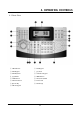
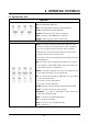
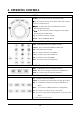

4. OPERATING CONTROLS
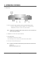
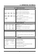
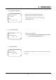
4.2 Rear View
① RS-232 : This connector port is provided to connect the external modem for remote
monitoring, configuration and software upgrades. Use a modem cable with
ADB-9S(female) connector to connect to the Cyber controller.
Notice : A Modem cable not supplied so make certain you have the correct cable when you
connect to the Cyber controller.
② ID DIP Switch : It is used to select Cyber controller ID.
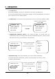
③ RJ-45 JACK (IN/OUT)
IN : Data Input port from the slave controller.
OUT : Data output port to the another devices, dome camera, matrix, DVR etc.
④ DC 12V Jack : DC 12V/1A Power Input jack.
Note : - You must use the adaptor provided with the product. Otherwise it would not work.
(DC 12V, 1A)
- We do not provide the power cord.
12